Magnetometer X-Y-Z
Get measurement of magnetic field along the X, Y, and Z axes of the Magnetometer
Since R2023b
Libraries:
Simulink Coder Support Package for BBC micro:bit/Magnetometer
Description
The Magnetometer X-Y-Z block measures the magnetic field along the X, Y,
and Z axes. The block has three output ports. The Magnet port outputs the magnetic field as
a [1x3] vector in uT.
Use the parameters of this block to select the Output Data Rates (ODR) for the
magnetometer. The Output Data Rates (ODR) range from 0.63 Hz to
80 Hz.
The Magnetometer X-Y-Z block supports BBC micro:bit board versions V1.3, V1.5, and V2.2.
This block consists of MAG3110 3-Axis Magnetometer and LSM303 3-axes Magnetometer sensors.
Note
The LSM303 3-axes Magnetometer sensor supports V1.5, and V2.2 boards and MAG3110 3-Axis Magnetometer sensor supports V1.3 board.
Chip Orientation and Axis Orientation Relative to Gravity
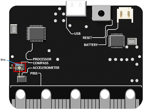
Hold the board so that the board faces you and the line to the top of the MAG3110 3-Axis chip is aligned horizontally to the table. At this position, the X-axis is horizontal and points to the left, the Y-axis is vertical and points down, and the Z-axis points toward you.
The direction of the arrows shows the positive direction of the reading for the magnetometer.

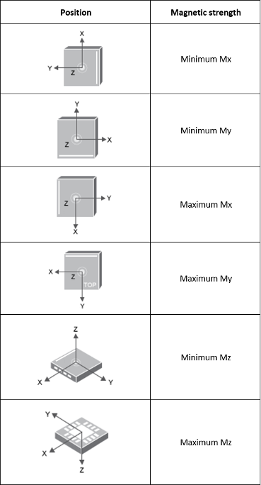
When you tilt the board along the X, Y, and Z axes of the chip, this illustration shows the strength of the magnetic field.

Hold the board so that the board faces you, and the line to the right of the chip
is aligned vertically to the table. The magnetometer on the chip measures the earth
magnetic field along each sensor axis. In the resultant [1x3]
vector, the first value that represents the magnetic strength at the X-axis is
minimum.
Ports
Output
Parameters
Version History
Introduced in R2023b