SDA Optical Communications Terminal Link-Level Simulation
This example shows how to measure the bit error rate (BER) in an optical communication system using the Optical Communications Terminal (OCT) standard 4.0.0. The Space Development Agency (SDA) developed this standard to enable interoperability among free-space optical (FSO) systems where at least one endpoint is a space-based terminal. The OCT standard supports these scenarios.
Space-to-space (S2S)
Space-to-air (S2A)
Space-to-maritime (S2M)
Space-to-ground (S2G)
SDA OCT 4.0.0 defines the technical requirements for optical terminals that operate in a large constellation of optically interconnected satellites in low Earth orbit (LEO). The standard supports low-latency data transport, and advanced space-based sensing and tracking capabilities. The SDA OCT 4.0.0 waveforms also enable satellites in medium Earth orbit (MEO) to connect into the Transport Layer. These waveforms have been developed to accommodate challenging link conditions, including long-range crosslinks up to 20,000 km.
SDA OCT Receiver Architecture
This figure shows the internal organization of SDA OCT signaling, including both the channel and the receiver.
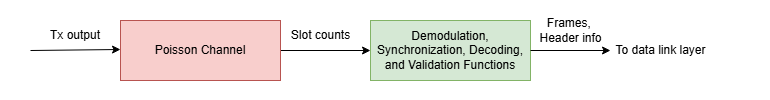
The receiver accepts the output slot counts from the Poisson channel, where each slot count represents the estimated number of detected photons in that time slot. The receiver demodulates the received slot counts, synchronizes the frame, decodes the payload, and validates frame integrity to recover the transmitted frames. After successfully recovering the frames, the receiver passes them to the data link layer for further processing.
In this example, the receiver recovers both data frames and management frames, and excludes idle frames from further processing. The receiver also extracts key signaling information from each frame header, such as frame sequence numbers (FSN), acknowledgment status, and additional protocol fields. This signaling information enables reliable communication, robust error handling, and integration with higher protocol layers. The example extracts the signaling information from each header into a structure, headerInfo, with these fields:
FrameType— Type of frame: "data" or "management".FrameSequenceNumber— Unique sequence number assigned to each frame for tracking and ordering.ARQMaxRetransmissions— Maximum number of allowed retransmissions for a frame.ARQHoldOffSpan— Minimum number of frames to wait before retransmitting, managing the retransmission timing.RetransmissionCount— Current number of retransmissions for the frame.HasAck— Flag indicating whether this frame includes acknowledgment (ACK) information.AckStatus— Status of the ACK.AckStartSequenceNum— Starting sequence number for ACK coverage, identifying which frames are being acknowledged.AckSpan— Span of frames covered by the acknowledgment.LDPCRateID— Low density parity check (LDPC) code rate identifier, used for payload error correction.TODEpoch— The time-of-day epoch field, providing a timestamp for the frame.PicoSecInTODEpoch— Picoseconds within the epoch, for precise frame timing.TODEpochFrameOffset— Frame offset within the time-of-day epoch, used for synchronization.FCCHOpcode— Fast command and control header (FCCH) opcode, indicating special command or control information.FCCHPayload— Payload associated with the FCCH opcode, carrying command or control data.CRCError— Flag indicating whether the cyclic redundancy check (CRC) has passed or failed.
Configure Simulation Parameters
Specify the configuration parameters for SDA waveform generation and data recovery. You can adjust the number of frames, average signal photons per pulsed slot, average noise photons per slot, and modulation settings to observe their impact on the simulation.
% Channel parameters cfgParams.NumSignalPhotons = [4 4.5 4.7 4.9 5.1]; % Average number of signal photons per pulsed slot cfgParams.NumNoisePhotons = 4; % Average number of noise photons per slot % Configure number of frames cfgParams.NumDataFrames = 3; cfgParams.NumIdleFrames = 2; % Configure ARQ parameters cfgParams.ARQMaxRetransmissions = 2; % Maximum allowable retransmission attempts cfgParams.RetransmissionsCount = 1; % Current retransmission attempt number cfgParams.HasAck = [1 1 0]; % Indicates if an acknowledgement (ACK) is present in the frame cfgParams.AckStatus = [1 0 0]; % Acknowledgement status cfgParams.AckStartSequenceNum = [12 20 0]; % Sequence number of the initial ACK frame % Configure modulation parameters cfgParams.ModulationFormat ="Manchester-BM12"; % OOK-NRZ|Manchester|Manchester-BM12|Manchester-BM16 cfgParams.AMFrequency =
50e3; % AM tone frequency in Hz (40 kHz or 50 kHz) if ~contains(cfgParams.ModulationFormat,"Manchester-BM") cfgParams.LDPCRateID = [2 1 3]; cfgParams.ModulationIndex = 0.33; cfgParams.SignalingRate =
2500e6; end cfgParams.MaxLDPCIterations = 20;
Generate SDA OCT Waveforms
Generate three payload data frames. Assign each data frame a unique FSN for tracking and management. Insert idle frames as needed to maintain synchronization or fill gaps when no payload data is available.
% Initialize frame sequence numbers
dataFSN = 1:cfgParams.NumDataFrames;
idleFSN = dataFSN(end) + (1:cfgParams.NumIdleFrames);
% Generate data frames
frameLength = 8416;
dataBits = randi([0 1],frameLength,cfgParams.NumDataFrames);
Create an instance of the HelperSDAOCTWaveformGenerator System object™, and configure the automatic repeat request (ARQ) and modulation parameters. For more information on waveform generation, see the SDA Optical Communication Terminal Waveform Generation example.
% Create and configure SDA OCT waveform generator
wavegenObj = HelperSDAOCTWaveformGenerator;
wavegenObj.ARQMaxRetransmissions = cfgParams.ARQMaxRetransmissions;
wavegenObj.RetransmissionCount = cfgParams.RetransmissionsCount;
wavegenObj.HasAck = cfgParams.HasAck;
wavegenObj.AckStatus = cfgParams.AckStatus;
wavegenObj.AckStartSequenceNum = cfgParams.AckStartSequenceNum;
wavegenObj.AMFrequency = cfgParams.AMFrequency;

wavegenObj.ModulationFormat = cfgParams.ModulationFormat;
if ~contains(cfgParams.ModulationFormat,"Manchester-BM")
    wavegenObj.LDPCRateID = cfgParams.LDPCRateID;
    wavegenObj.ModulationIndex = cfgParams.ModulationIndex;
    wavegenObj.SignalingRate = cfgParams.SignalingRate;
end
BER Processing Loop
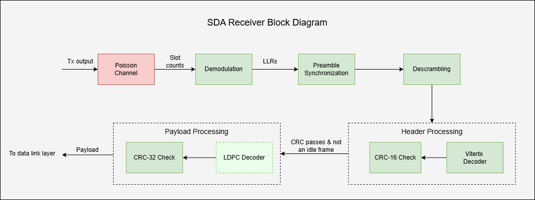
This example shows you the steps to analyze the BER performance of an SDA OCT optical link by simulating channel effects and receiver processing. The figure outlines the channel and processing stages of the SDA receiver, from demodulation to payload decoding, involved in this process.
Simulate Optical Poisson Channel
This example transmits the modulated data through the channel using the dsocPoissonChannel System object. This object models the channel as a Poisson point process. You can set the NumSignalPhotons property to different values to represent different intensity levels. At each level, the transmitted data follows a Poisson distribution. The channel object adds background noise and simulates the photon detection process by estimating the photon count in each time slot at the receiver.
Receiver Processing
This example processes the slot counts from the channel and recovers the payload using these steps.
Demodulate Received Photon Counts to LLRs
Demodulate the received photon counts into log-likelihood ratios (LLRs) using the HelperSDAOCTDemodulator System object. Configure the demodulator properties (SignalingRate, AMFrequency, ModulationIndex, ModulationFormat, and PeakPower) to match the transmitter settings. The demodulator calculates the LLRs based on the mean number of signal photons per pulsed slot and the estimated mean number of noise photons per slot. It estimates the noise level by identifying non-pulsed slots in the received signal.
Prior to SDA OCT standard 4.0.0, the SDA specification used synchronous, continuous transmission with on-off keying (OOK) modulation, encoded with either the non-return-to-zero (NRZ) or Manchester format. These formats support data rates up to 2.2 Gbps and include a 40 kHz or 50 kHz tracking tone for proliferated low Earth orbit (pLEO) satellite links. To support long-range FSO links (MEO and LEO up to 20,000 km), SDA OCT 4.0.0 introduces two burst-mode Manchester formats: Manchester-BM12 and Manchester-BM16. These formats, with duty cycles of 1/12 and 1/16, respectively, provide lower user data rates of 48.9 Mbps and 36.7 Mbps, but enhance robustness for long-range FSO links.
% Initialize SDA OCT demodulator object matched with transmitter settings
demodObj = HelperSDAOCTDemodulator;
demodObj.SignalingRate = wavegenObj.SignalingRate;
demodObj.AMFrequency = wavegenObj.AMFrequency;
demodObj.ModulationIndex = wavegenObj.ModulationIndex;
demodObj.ModulationFormat = wavegenObj.ModulationFormat;
Detect Frame Preamble
Each transmitted frame starts with a fixed 64-bit preamble that enables frame synchronization at the receiver. Detect the preamble by performing a soft correlation between the received LLRs and the known preamble sequence, which is the sync marker. Apply a detection threshold to the correlation output to detect the presence of the preamble. After successful preamble detection, extract and forward the encoded header and payload sections of the frame for further processing.
% Initialize parameters for frame synchronization
preambleLen = 64;
preambleBits = hex2poly("53225B1D0D73DF03")';
softPreamble = 2*preambleBits - 1;            % Convert to soft bits +1/-1
corrThreshold = 0.5;                          % Threshold for detection
Recover Header Information
Extract the header from the frame-synchronized LLRs and use the HelperSDAOCTHeaderRecover function to decode and verify the frame header. This function performs soft Viterbi decoding and CRC-16 validation to ensure header integrity. If decoding succeeds, it extracts the header information into the headerInfo structure. If the FrameType is not "idle" and the CRC check passes, forward the payload portion of the frame for data recovery. For idle frames, recover only the information in the header and ignore the payload.
% Preallocate header fields for all possible received frames
maxRxFrames = cfgParams.NumIdleFrames + cfgParams.NumDataFrames;
headerConfig = struct("ARQMaxRetransmissions",0, ...
    "ARQHoldOffSpan",0, ...
    "FrameSequenceNumber",zeros(1,maxRxFrames), ...
    "FrameType",strings(1,maxRxFrames), ...
    "RetransmissionCount",zeros(1,maxRxFrames), ...
    "HasAck",false(1,maxRxFrames), ...
    "AckStatus",false(1,maxRxFrames), ...
    "AckStartSequenceNum",zeros(1,maxRxFrames), ...
    "AckSpan",zeros(1,maxRxFrames), ...
    "LDPCRateID",zeros(1,maxRxFrames), ...
    "TODEpoch",zeros(1,maxRxFrames), ...
    "PicoSecInTODEpoch",zeros(1,maxRxFrames), ...
    "TODEpochFrameOffset",zeros(1,maxRxFrames), ...
    "FCCHOpcode",ones(6,maxRxFrames), ...
    "FCCHPayload",ones(16,maxRxFrames), ...
    "CRCError",false(1,maxRxFrames));
Descramble Payload
Descramble the payload using the known scrambling sequence. For each bit position:
If the scrambling bit is
0, leave the LLR unchanged.If the scrambling bit is
1, invert the sign of the LLR.
Pass the resulting descrambled LLR sequence to LDPC decoder for payload recovery.
% Initialize PN sequence for descrambling (covers header + max payload)
encodedHeaderLen = 960;
LDPCOutputLens = [8448 9984 11136 12672 16896];
maxLDPCLen = max(LDPCOutputLens);
pnSeqObj = comm.PNSequence(SamplesPerFrame=encodedHeaderLen+maxLDPCLen, ...
    Polynomial="z^15 + z + 1", ...
    InitialConditions=[0 0 0 0 1 1 0 1 1 0 1 1 1 0 0]);
softPNSeq = 1 - 2*pnSeqObj();
LDPC Decode and CRC Check
Use the HelperSDAOCTLDPCDecode function to perform LDPC decoding on the payload portion of the received frame. This function uses the LDPC rate identifier from the header to decode the payload LLRs. After decoding, apply a CRC-32 check to validate payload integrity. The CRC-32 result indicates whether the payload was successfully recovered.
% CRC-32 configuration for payload verification
crc32Cfg = crcConfig( ...
    Polynomial=[32 26 23 22 16 12 11 10 8 7 5 4 2 1 0], ...
    InitialConditions=0,DirectMethod=true);
Compute BER
For each successfully decoded frame, this example compares the recovered payload bits against the corresponding transmitted payload bits to calculate the BER.
% Ensure reproducibility for each run
rng("default")

% BER preallocation for all photon levels
ber = zeros(length(cfgParams.NumSignalPhotons),1);

% Main simulation loop over signal photon levels
for nsIdx = 1:length(cfgParams.NumSignalPhotons)
    % Display the current slot index
    ns = cfgParams.NumSignalPhotons(nsIdx);
    disp("For ns = " + ns)
    % Generate waveform for data frames
    wavegenObj.PeakPower = ns;
    wavegenObj.FrameType = "data";
    dataWaveform = wavegenObj(dataFSN,dataBits(:));

    % Generate waveform for idle frames
    wavegenObj.FrameType = "idle";
    idleWaveform = wavegenObj(idleFSN,cfgParams.NumIdleFrames);

    % Concatenate data and idle waveforms for transmission
    txOutput = [dataWaveform; idleWaveform];

    % Poisson photon counting with quantization
    quantizedIntensity = floor(txOutput*10)/10;                                   % Quantize to 0.1
    uniqueLevels = unique(quantizedIntensity);
    slotCounts = zeros(length(txOutput),1);
    channelObj = dsocPoissonChannel(NumNoisePhotons=cfgParams.NumNoisePhotons);
    % Process each unique intensity level through the Poisson channel
    for idxLevel = 1:length(uniqueLevels)
        intensity = uniqueLevels(idxLevel);
        channelObj.NumSignalPhotons = intensity;
        pulseIdx = (quantizedIntensity == intensity);
        slotCounts(pulseIdx) = channelObj(ones(nnz(pulseIdx),1));
        release(channelObj)
    end

    % Demodulate photon counts to LLRs
    demodObj.PeakPower = ns;
    llr = demodObj(slotCounts);

    % Initialize parameters for frame synchronization
    codeLen = length(llr);
    payloadCount = 0;
    frameCount = 0;
    startIdx = 1;

    % Preallocate output variables
    payload = zeros(frameLength,maxRxFrames);
    crcErrors = zeros(maxRxFrames,1);
    headerInfo = headerConfig;

    while (startIdx + preambleLen - 1) <= codeLen
        % Correlation for preamble detection
        corrWindow = llr(startIdx:(startIdx+preambleLen-1));
        normCorr = xcorr(corrWindow,softPreamble,0,"normalized");

        if normCorr>=corrThreshold && ...
                (startIdx+preambleLen+encodedHeaderLen-1)<=codeLen

            % Extract header LLRs and decode
            headerStIdx = startIdx + preambleLen;
            headerEndIdx = headerStIdx + encodedHeaderLen - 1;
            headerParams = HelperSDAOCTHeaderRecover(llr(headerStIdx:headerEndIdx));

            %  If the CRC passes, copy header fields and proceed to
            %  payload processing
            if ~headerParams.CRCError
                frameCount = frameCount + 1;
                % Initialize nontunable parameters for first frame only
                if frameCount == 1
                    headerInfo.ARQMaxRetransmissions = headerParams.ARQMaxRetransmissions;
                    headerInfo.ARQHoldOffSpan = headerParams.ARQHoldOffSpan;
                end
                headerInfo.FrameSequenceNumber(frameCount) = headerParams.FrameSequenceNumber;
                headerInfo.FrameType(frameCount) = headerParams.FrameType;
                headerInfo.RetransmissionCount(frameCount) = headerParams.RetransmissionCount;
                headerInfo.HasAck(frameCount) = headerParams.HasAck;
                headerInfo.AckStatus(frameCount) = headerParams.AckStatus;
                headerInfo.AckStartSequenceNum(frameCount) = headerParams.AckStartSequenceNum;
                headerInfo.AckSpan(frameCount) = headerParams.AckSpan;
                headerInfo.LDPCRateID(frameCount) = headerParams.LDPCRateID;
                headerInfo.TODEpoch(frameCount) = headerParams.TODEpoch;
                headerInfo.PicoSecInTODEpoch(frameCount) = headerParams.PicoSecInTODEpoch;
                headerInfo.TODEpochFrameOffset(frameCount) = headerParams.TODEpochFrameOffset;
                headerInfo.FCCHOpcode(:,frameCount) = headerParams.FCCHOpcode;
                headerInfo.FCCHPayload(:,frameCount) = headerParams.FCCHPayload;

                % Compute LDPC indices
                ldpcLen = LDPCOutputLens(headerParams.LDPCRateID + 1);
                ldpcStIdx = headerEndIdx + 1;
                ldpcEndIdx = ldpcStIdx + ldpcLen - 1;

                % Process payload for only non-idle frames
                if ~strcmp(headerParams.FrameType,"idle") && ldpcEndIdx<=codeLen

                    % Descrambling
                    pn = softPNSeq((encodedHeaderLen+1):(encodedHeaderLen+ldpcLen));
                    ldpcInput = llr(ldpcStIdx:ldpcEndIdx).*pn;

                    % LDPC Decoding
                    ldpcDecoded = HelperSDAOCTLDPCDecode(-ldpcInput,headerParams.LDPCRateID,cfgParams.MaxLDPCIterations);

                    % CRC-32 Detection
                    payloadCount = payloadCount + 1;
                    [payload(:,payloadCount),crcErrors(payloadCount)] = crcDetect(ldpcDecoded,crc32Cfg);
                end
                % Advance to end of LDPC for next search
                startIdx = ldpcEndIdx + 1;
            else
                % Header CRC failed, shift by 1 and keep searching
                startIdx = startIdx + 1;
            end
        else
            % Correlation did not pass, or header exceeds buffer
            startIdx = startIdx + 1;
        end
    end

    % Extract received payload frames and CRC status
    if payloadCount > 0
        % Extract the received payload and CRC error up to the number of
        % received frames
        rxPayload = payload(:,1:payloadCount);
        crcErrorStatus = crcErrors(1:payloadCount);
    else
        % No payload frames received
        rxPayload = [];
        crcErrorStatus = [];
    end

    % Identify received frame sequence numbers, excluding idle frames
    if frameCount > 0
        % Find non-idle frames based on FrameType
        nonIdleFrames = ~strcmp(headerInfo.FrameType(1:frameCount),"idle");
        % Get frame sequence numbers for non-idle frames
        rxFSN = headerInfo.FrameSequenceNumber(nonIdleFrames);
    else
        % No frames received
        rxFSN = [];
    end
    rxFSN = rxFSN(1:size(rxPayload,2));

    % Determine lost frames by comparing transmitted and received FSNs
    txFSN = dataFSN;
    lostFSN = setdiff(txFSN,rxFSN);
    if ~isempty(lostFSN)
        disp("* Data frames with FSN = " + num2str(lostFSN) + "are lost")
    end

    % Calculate the BER for the received payload frames
    if ~isempty(rxPayload) && ~isempty(rxFSN)
        % Align received FSN indices with transmitted FSNs to maintain order
        [~,~,rxIndices] = intersect(rxFSN,txFSN,"stable");

        if ~isempty(rxIndices)
            txBits = dataBits;
            % Reference bits corresponding to received FSNs
            refBits = txBits(:,rxIndices);

            % Compute bit errors and BER
            numBitErrors = nnz(rxPayload ~= refBits);
            ber(nsIdx) = numBitErrors/numel(refBits);

            disp("* BER for received FSN(s) " + num2str(rxFSN) + " is " + num2str(ber(nsIdx)))
            disp("* CRC Error = " + num2str(crcErrorStatus'))
            disp(" ") % New line for readability
        end
    end

    release(wavegenObj)
    release(demodObj)
end
For ns = 4
* BER for received FSN(s) 1 2 3 is 0.19166
* CRC Error = 1 1 1
For ns = 4.5
* BER for received FSN(s) 1 2 3 is 0.15728
* CRC Error = 1 1 1
For ns = 4.7
* BER for received FSN(s) 1 2 3 is 0.11054
* CRC Error = 1 1 1
For ns = 4.9
* BER for received FSN(s) 1 2 3 is 0.060005
* CRC Error = 1 1 1
For ns = 5.1
* BER for received FSN(s) 1 2 3 is 0.029705
* CRC Error = 1 1 1
Visualize Simulation Results
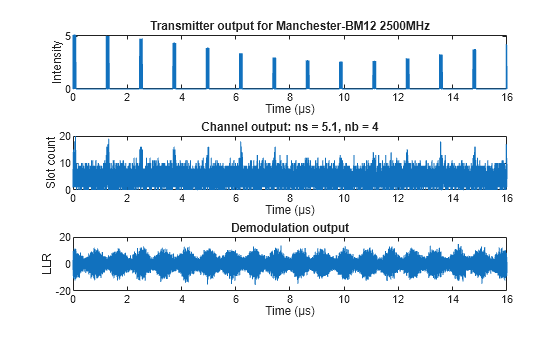
Plot the transmitted intensity, received photon counts, and LLRs.
% Number of samples for visualization
samplesToPlot = min(4e4,numel(txOutput));

tsamp = 1/double(wavegenObj.SignalingRate);
t = 0:tsamp:(samplesToPlot-1)*tsamp;

figure
subplot(3,1,1)
plot(t*1e6,txOutput(1:samplesToPlot))
xlabel("Time (µs)")
ylabel("Intensity")
title("Transmitter output for " + wavegenObj.ModulationFormat + " " + num2str(wavegenObj.SignalingRate/1e6)+"MHz")

subplot(3,1,2)
plot(t*1e6,slotCounts(1:samplesToPlot))
xlabel("Time (µs)")
ylabel("Slot count")
title("Channel output: ns = " + num2str(ns) + ", nb = " + num2str(cfgParams.NumNoisePhotons))

subplot(3,1,3)
plot(t*1e6,llr(1:samplesToPlot))
xlabel("Time (µs)")
ylabel("LLR")
title("Demodulation output")
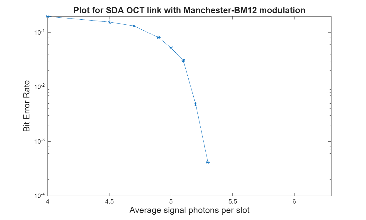
Visualize the BER results. Plot the average number of signal photons per slot on the x-axis and BER on the y-axis.
figure
semilogy(cfgParams.NumSignalPhotons,ber,"-*");
xlim([cfgParams.NumSignalPhotons(1) cfgParams.NumSignalPhotons(end)+1])
title("Plot for SDA OCT link with " + wavegenObj.ModulationFormat + " modulation")
xlabel("Average signal photons per slot (ns)")
ylabel("Bit Error Rate")
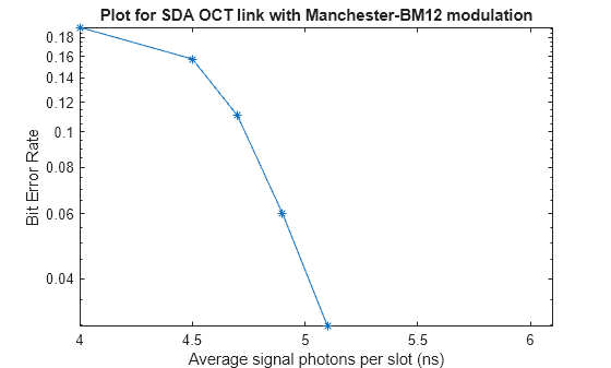
This figure shows the BER analysis for the Poisson channel in an SDA OCT link for 15 frames with ARQMaxRetransmissions set to 0.
Further Exploration
You can use this example to further explore these options:
To analyze the BER for various modulation formats, change the
ModulationFormatto"OOK-NRZ","Manchester","Manchester-BM12", or"Manchester-BM16". Then, observe their impact on system performance.To analyze the BER for OOK-NRZ and Manchester modulation without amplitude tone modulation, set the
ModulationIndexparameter to0.To evaluate the BER under different noise and signal conditions, modify the
NumSignalPhotonsandNumNoisePhotonsfields of thecfgParamsstructure.
Supporting Files
The example uses these helper functions and objects:
HelperSDAOCTDemodulator.m— Performs SDA OCT demodulationHelperSDAOCTHeaderRecover.m— Recovers header parametersHelperSDAOCTLDPCEncode.m— Performs SDA OCT LDPC encodingHelperSDAOCTLDPCDecode.m— Performs SDA OCT LDPC decodingHelperSDAOCTModulator.m— Performs SDA OCT modulationHelperSDAOCTWaveformGenerator.m— Generates an SDA OCT waveform
References
[1] Space Development Agency (SDA). Optical Communications Terminal (OCT) Standard Version 4.0.0. Washington DC: SDA United States Space Force, June 28, 2024.
[2] 3GPP TS 38.212. “NR; Multiplexing and channel coding.” 3rd Generation Partnership Project; Technical Specification Group Radio Access Network.