Main Content

Crankshaft

Combustion engine crankshaft that connects to one or more pistons

Since R2022a

Libraries:
Simscape / Driveline / Engines & Motors / Engine Subcomponents

Description

The Crankshaft block represents the crankshaft component of an abstracted internal combustion engine. Connect this block to one or more SI Combustion Cylinder blocks to compute the crank-angle-resolved instantaneous torque.

Equations

The generic torque-speed-power relationship governs the block, such that

τω=P,

where

  • τ is the torque.

  • ω is the rotational speed, which the block assumes is nonnegative.

  • P is the power.

The block calculates the power as

P=i=1NPi,

where N is the value of the Number of cylinders parameter. The block calculates ω as the time derivative of the crank position, θ, such that

ddtθ=ω.

The constant ωc is the Threshold to avoid divide-by-zero parameter. When ω < ωc, the block applies 1/ω linearization.

τ={PωP(2ωωωc2)ωωcω<ωc

Crank Position

The block calculates the crank position with respect to the top dead center position for each combustion cylinder, where 0 ≤ θi ≤ 720 degrees. How the block performs this calculation depends on N. For all values of N, θ1 = θ. For N = 2, θ2 = θ1+Δ, where Δ is the Spark angle difference parameter. This parameter value is specific to the engine you want to model. It may be a value such as 270° or 360°. When N = 3, the block assumes that the cylinders are evenly phased such that

θ2=θ1+(17203)θ3=θ1+(27203)

When N = 4, the block assumes that the cylinders are evenly phased at 180° and enables the Firing order parameter.

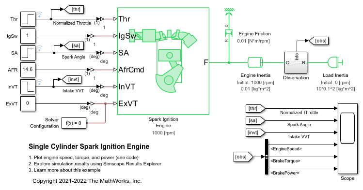
Examples

Ports

Input

expand all

Physical signal input associated with the cylinder power when the block acts as a subcomponent.

Dependencies

To enable this port, set Input power separately to Off.

Physical signal input associated with the power from cylinder 1.

Dependencies

To enable this port, set Input power separately to On.

Physical signal input associated with the power from cylinder 2.

Dependencies

To enable this port, set Number of cylinders to Two Cylinders, Three Cylinders, or Four Cylinders and Input power separately to On.

Physical signal input associated with the power from cylinder 3.

Dependencies

To enable this port, set Number of cylinders to Three Cylinders or Four Cylinders and Input power separately to On.

Physical signal input associated with the power from cylinder 4.

Dependencies

To enable this port, set Number of cylinders to Four Cylinders and Input power separately to On.

Output

expand all

Physical signal output associated with the crank position, in degrees.

Physical signal output associated with the engine rotational speed, in rad/s.

Physical signal output associated with the cycle-average crank speed, in rad/s.

Physical signal output associated with the cycle-average net-indicated crank torque, in Nm.

Physical signal output associated with the instantaneous net-indicated crank torque, in Nm.

Conserving

expand all

Mechanical rotational conserving port associated with the crankshaft follower.

Parameters

expand all

Mechanical

Initial crank position.

Number of spark ignition cylinders.

Whether to input power as an array or to assign each combustion cylinder to its own port.

Spark angle difference for two cylinder engines. This value can vary from engine to engine.

Dependencies

To enable this parameter, set Number of cylinders to Two Cylinders.

Firing order for four-cylinder engines. Firing order is engine-specific, but your selection for this parameter will not affect the block performance. You can use the firing order information for controller development.

Dependencies

To enable this parameter, set Number of cylinders to Four Cylinders.

Simulation

Engine rotational speed at which the block applies linearization to avoid discontinuities at ω = 0.

Output

Whether to output the cycle-average speed.

Whether to output the cycle-average net indicated torque.

Whether to output the instantaneous net indicated torque.

Version History

Introduced in R2022a