Cycloidal Drive
High-ratio speed reducer based on cycloidal disc motion
Libraries:
Simscape /
Driveline /
Gears
Description
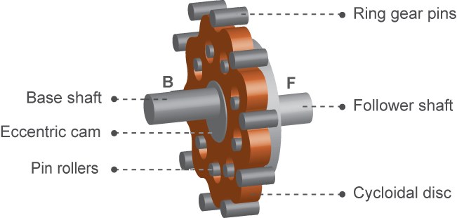
The Cycloidal Drive block represents a compact, high-ratio, speed-reduction mechanism that contains four key components:
A cycloidal disc
An eccentric cam
Ring-gear housing
Pin rollers
The eccentric cam, which extends from the base shaft, sits inside the cycloidal disc. This disc meshes with the ring-gear housing. The pin rollers, which extend from the follower shaft, sit in matching holes on the cycloidal disc.

During normal operation, the base shaft drives the eccentric cam. The cam spins inside the cycloidal disc, causing it to rotate in an eccentric pattern about an offset axis. As it moves, the cycloidal disc engages the internal teeth of the ring-gear housing. The internal meshing reverses the rotational velocity direction.
The pin rollers extending through the cycloidal disc holes transmit rotational motion to the follower shaft. This shaft spins counter to the base shaft at a very reduced speed. The high reduction ratio results from the near-equal cycloidal disc and ring gear tooth numbers. The block calculates the effective gear reduction ratio as
where:
r is the gear reduction ratio.
nR is the number of teeth on the ring gear.
nC is the number of teeth on the cycloidal disc.
The gear reduction ratio constrains the angular velocities of the base and follower shafts according to the expression
where:
ωF is the angular velocity of the follower shaft.
ωC is the angular velocity of the base shaft.
The gear reduction ratio also constrains the torques acting on the base and follower shafts, according to the expression
where:
TB is the net torque at the base shaft.
TF is the net torque at the follower shaft.
Tf is the torque loss due to friction. For more information, see Model Gears with Losses.
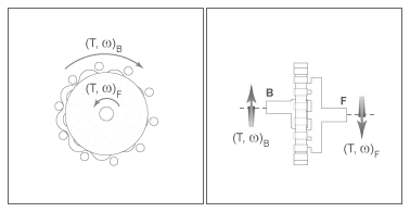
The figure shows the cycloidal drive in front and side views. The kinematics of the drive system cause a reversal of the base and follower shaft angular velocities so that the two shafts spin in opposite directions.

The cycloidal drive can operate in reverse mode, that is, with power flowing from the follower shaft to the base shaft. In reverse mode, torque transfer efficiencies are typically negligible. You can adjust the efficiency by changing the value of the Efficiency from follower shaft to base shaft parameter.
Ring Gear Rotation
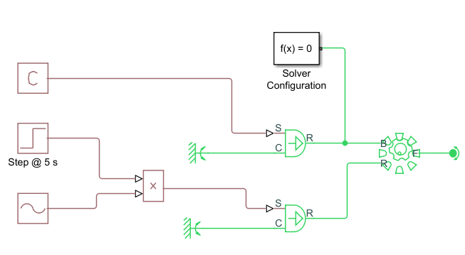
When you select Ring gear rotation, the block exposes port R, which allows you to simulate the rotational motion of the ring gear by using a mechanical rotational input signal. The block implements this motion as
where τr is the net torque at the ring gear. The figures demonstrate how applying a sine wave to the ring gear causes small adjustments to the follower shaft while maintaining a constant base shaft speed.


Friction Model
You can set Friction model to:
No meshing losses - suitable for HIL
                                simulation
, which ignores losses to maintain an suitable computation time for HIL simulation.Constant efficiency, which lets you specify a component efficiency that remains constant through the simulation. This is the default friction setting for block versions prior to R2020b.Temperature-dependent efficiency, which models temperature-dependent component efficiencies by creating a 1-D lookup table based on the Temperature vector and the given component efficiency vector. This setting also exposes the thermal conserving port H. Port H receives the heat flow into the block, which is translated into the block temperature according to the value of the Thermal mass parameter.
Thermal Model
You can model
the effects of heat flow and temperature change by enabling the optional thermal port. To enable
the port, set Friction model to Temperature-dependent
efficiency.
Variables
Use the Variables settings to set the priority and initial target values for the block variables before simulating. For more information, see Set Priority and Initial Target for Block Variables.
