主要内容

Three-Axle Vehicle Body

Vehicle body with three axles

Since R2026a

Libraries:
Simscape / Driveline / Tires & Vehicles

Description

The Three-Axle Vehicle Body block represents a three-axle vehicle in longitudinal motion. You can specify the number of wheels for each axle. The block accounts for body mass, aerodynamic drag, road incline, pitch and heave, and weight distribution between axles due to acceleration and road profile. The vehicle mass and center of gravity remain constant.

Vehicle Model

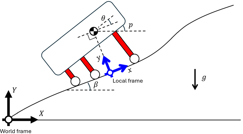
The vehicle axles are parallel and form a plane. The local frame moves with the center of gravity. The x-axis is tangential to the road surface in the direction of forward motion, while the y-axis points to the center of gravity.

If the vehicle travels on an inclined road, the normal direction, y, is not parallel to gravity but is always perpendicular to the axle-longitudinal plane. θ is the relative pitch angle between the road inclination angle, β, and the angle of the vehicle. p = θ+β, where p is the pitch angle, measured against the X-axis of the world frame.

The y-axis of the local frame that defines the vehicle vertical position is normal to the road surface and points to the center of gravity of the vehicle.

Equations

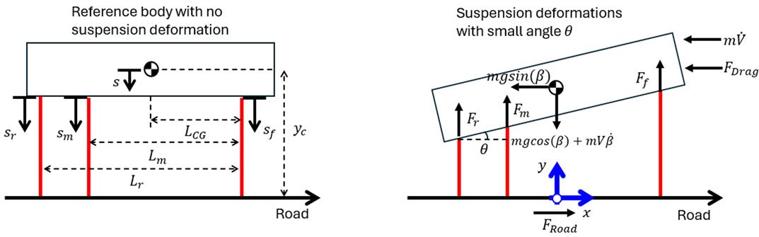
The block balances force in the x and y-directions, such that

mx¨CG=0=FroadFdragmgsin(β)mv˙my¨CG=(Ff+Fm+Fr)mgcos(β)mv˙β

where:

  • m is the mass of the vehicle.

  • xCG and yCG are the positions of the center of gravity along the x-axis and y-axis, respectively.

  • Froad is the force of the road acting on the vehicle in the x-direction.

  • Fdrag is the force due to drag acting on the vehicle in the x-direction.

  • g is the gravitational acceleration.

  • v is the vehicle velocity tangential to the road surface.

  • Ff, Fm, and Fr are the forces applied to the front, middle, and rear suspension in the y-direction, respectively.

The block defines the horizontal locations of the center of gravity (CG), middle axis, and rear axle with respect to the location of the front axle. The figure shows the vehicle body with and without suspension deformation.

The left figure shows the vehicle body without any suspension deformations, and the right figure shows the vehicle body with arbitrary suspension deformation.

The block balances torque about the CG, such that

τCG=I¨p=LCGFf(LmLCG)Fm(LrLCG)Fr+(ycs)Froad,

where:

  • I is the pitch moment of inertia of the vehicle.

  • LCG is the distance from the front axle to the CG along the x-axis.

  • Lm is the distance from the front axle to the middle axle along the x-axis.

  • Lr is the distance from the front axle to the rear axle along the x-axis.

  • yc is the height of the CG with no deformation.

  • s is the change in position of the CG due to suspension deformation, such that s = yc-yCG.

The block defines the forces at the front, middle, and rear suspensions, such that

Ff=Ff,suspension(sf,s˙f)+Ff,hardstop(sf,s˙f)Fm=Fm,suspension(sm,s˙m)+Fm,hardstop(sm,s˙m)Fr=Fr,suspension(sr,s˙r)+Fr,hardstop(sr,s˙r)

where:

  • Ff,suspension, Fm,suspension, Fr,suspension are the forces transmitted by the front, middle, and rear suspension, respectively.

  • Ff,hardstop, Fm,hardstop, and Fr,hardstop are the forces applied by the hard stops at the front, middle, and rear suspensions, respectively.

The figure illustrates the geometric relationships.

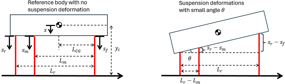
The block leverages the small angle and rigid body assumptions to simplify calculations, such that

θ=srsfLrsrsmLrLm=srsfLr

The block calculates the height change of the CG due to deformation, such that

s=srθ(LrLCG).

When you select the Enable hard stops parameter, the block uses a subcomponent implementation of the Translational Hard Stop block, where the setting of the Hard stop model parameter is Stiffness and damping applied smoothly through transition region, damped rebound.

Ports

Input

expand all

Physical signal input port associated with the headwind speed, in m/s.

Physical signal input port associated with the drag coefficient.

Dependencies

To enable this port, select Variable Drag Coefficient.

Physical signal input port associated with the road incline angle, β, in rad.

Output

expand all

Physical signal output port associated with the longitudinal velocity of the vehicle, in m/s.

Physical signal output port associated with the front axle normal force, in N.

Physical signal output port associated with the middle axle normal force, in N.

Physical signal output port associated with the rear axle normal force, in N.

Conserving

expand all

Mechanical translational conserving port associated with the horizontal motion of the vehicle.

Parameters

expand all

Main

Mass of the vehicle.

Number of wheels on the front, middle, and rear axles. From left to right, the elements represent the number of wheels for the front, middle, and rear axles. For example, if the input is the array [2,4,4], then the front axle has two wheels, and the middle and rear axles have four wheels each.

Location of the center of gravity with respect to the front axle, LCCG.

Location of the middle axle with respect to the front axle, Lm.

Location of the rear axle with respect to the front axle, Lr.

Distance, yc, between the center of gravity of the vehicle and the ground.

Acceleration due to gravitational force acting at the center of gravity of the vehicle.

Option to generate a warning for negative normal force.

Time constant to filter inputs.

Drag

Effective cross-sectional area, A, presented by the vehicle in longitudinal motion. The block uses this value to calculate the aerodynamic drag force on the vehicle.

Whether the drag coefficient is variable. Enable this parameter to expose port CD.

Aerodynamic drag coefficient, CD. The block uses this value to calculate the aerodynamic drag force on the vehicle.

Dependencies

To enable this parameter, clear the Variable Drag Coefficient parameter.

Density of the air that surrounds the vehicle.

Pitch

Pitch moment of inertia of the vehicle, I.

Parameterization method to use to model the suspension. The setting determines how the block calculates Ff,suspension, Fm,suspension, and Fr,suspension. When you select Linear, you specify the front, middle, and rear stiffness and damping coefficients by using scalar values. When you select By table lookup, you specify the stiffness and damping forces and suspension deformation values as vectors.

Suspension stiffness at the front axle.

Dependencies

To enable this parameter, set the Suspension model parameter to Linear.

Suspension damping at the front axle.

Dependencies

To enable this parameter, set the Suspension model parameter to Linear.

Suspension stiffness at the middle axle.

Dependencies

To enable this parameter, set the Suspension model parameter to Linear.

Suspension damping at the middle axle.

Dependencies

To enable this parameter, set the Suspension model parameter to Linear.

Suspension stiffness at the rear axle.

Dependencies

To enable this parameter, set the Suspension model parameter to Linear.

Suspension damping at the rear axle.

Dependencies

To enable this parameter, set the Suspension model parameter to Linear.

Stiffness force at the front suspension. Each element in the vector corresponds to the elements in the Front suspension deformation vector parameter.

Dependencies

To enable this parameter, set the Suspension model parameter to By table lookup.

Front suspension deformation for a given stiffness force. Each element in the vector corresponds to the elements in the Front suspension stiffness vector parameter.

Dependencies

To enable this parameter, set the Suspension model parameter to By table lookup.

Damping force at the front suspension for a given velocity. Each element in the vector corresponds to the elements in the Front suspension velocity vector parameter.

Dependencies

To enable this parameter, set the Suspension model parameter to By table lookup.

Velocity of the front suspension. Each element in the vector corresponds to the elements in the Front suspension damping force vector parameter.

Dependencies

To enable this parameter, set the Suspension model parameter to By table lookup.

Stiffness force at the middle suspension. Each element in the vector corresponds to the elements in the Middle suspension deformation vector parameter.

Dependencies

To enable this parameter, set the Suspension model parameter to By table lookup.

Middle suspension deformation for a given stiffness force. Each element in the vector corresponds to the elements in the Middle suspension stiffness vector parameter.

Dependencies

To enable this parameter, set the Suspension model parameter to By table lookup.

Damping force at the middle suspension for a given velocity. Each element in the vector corresponds to the elements in the Middle suspension velocity vector parameter.

Dependencies

To enable this parameter, set the Suspension model parameter to By table lookup.

Velocity of the middle suspension. Each element in the vector corresponds to the elements in the Middle suspension damping force vector parameter.

Dependencies

To enable this parameter, set the Suspension model parameter to By table lookup.

Stiffness force at the rear suspension. Each element in the vector corresponds to the elements in the Rear suspension deformation vector parameter.

Dependencies

To enable this parameter, set the Suspension model parameter to By table lookup.

Rear suspension deformation for a given stiffness force. Each element in the vector corresponds to the elements in the Rear suspension stiffness vector parameter.

Dependencies

To enable this parameter, set the Suspension model parameter to By table lookup.

Damping force at the rear suspension for a given velocity. Each element in the vector corresponds to the elements in the Rear suspension velocity vector parameter.

Dependencies

To enable this parameter, set the Suspension model parameter to By table lookup.

Velocity of the rear suspension. Each element in the vector corresponds to the elements in the Rear suspension damping force vector parameter.

Dependencies

To enable this parameter, set the Suspension model parameter to By table lookup.

Interpolation method to use to approximate the output value when the input value is between two consecutive grid points. You can select:

  • Linear — Select this default option to get the best performance. Provide at least two values per dimension.

  • Smooth — Select this option to produce a continuous curve with continuous first-order derivatives. Provide at least three values per dimension.

For more information on interpolation algorithms, see PS Lookup Table (1D).

Dependencies

To enable this parameter, set the Suspension model parameter to By table lookup.

Extrapolation method to use to determine the output value when the input value is outside the specified operating range. You can select:

  • Linear — Produces a curve with continuous first-order derivatives in the extrapolation region and at the boundary with the interpolation region.

  • Nearest — Produces an extrapolation that does not go above the highest point in the data or below the lowest point in the data.

  • Error — Issues an error if the input signal is outside the range of the table. Select this option when you want your data to be within the table range.

For more information on extrapolation algorithms, see PS Lookup Table (1D).

Dependencies

To enable this parameter, set the Suspension model parameter to By table lookup.

Whether to initialize the block at pitch and heave equilibrium.

Pitch angle of the vehicle at the start of simulation.

Dependencies

To enable this parameter, clear the Initialize at pitch and heave equilibrium parameter.

Rate of change of the pitch at the start of simulation.

Dependencies

To enable this parameter, clear the Initialize at pitch and heave equilibrium parameter.

Height of the CG at the start of the simulation.

Vertical velocity of the CG at the start of the simulation.

Pitch Hard Stops

Whether to enable hard stops. The setting determines how the block calculates Ff,hardstop, Fm,hardstop, and Fr,hardstop.

Gap between the front axle slider and the front upper bound. Specify the direction with respect to the local coordinate system, with the slider located on the origin.

Dependencies

To enable this parameter, select the Enable hard stops parameter.

Gap between the front axle slider and the front lower bound. Specify the direction with respect to the local coordinate system, with the slider located on the origin.

Dependencies

To enable this parameter, select the Enable hard stops parameter.

Stiffness of the front suspension at the upper and lower bounds.

Damping of the front suspension at the upper and lower bounds.

Dependencies

To enable this parameter, select the Enable hard stops parameter.

Gap between the middle axle slider and the middle upper bound. Specify the direction with respect to the local coordinate system, with the slider located on the origin.

Gap between the middle axle slider and the middle upper bound. Specify the direction with respect to the local coordinate system, with the slider located on the origin.

Dependencies

To enable this parameter, select the Enable hard stops parameter.

Stiffness of the middle suspension at the upper and lower bounds.

Dependencies

To enable this parameter, select the Enable hard stops parameter.

Damping of the front suspension at the upper and lower bounds.

Dependencies

To enable this parameter, select the Enable hard stops parameter.

Gap between the rear axle slider and the rear upper bound. Specify the direction with respect to the local coordinate system, with the slider located on the origin.

Dependencies

To enable this parameter, select the Enable hard stops parameter.

Gap between the rear axle slider and the rear upper bound. Specify the direction with respect to the local coordinate system, with the slider located on the origin.

Dependencies

To enable this parameter, select the Enable hard stops parameter.

Stiffness of the rear suspension at the upper and lower bounds.

Dependencies

To enable this parameter, select the Enable hard stops parameter.

Damping of the rear suspension at the upper and lower bounds.

Dependencies

To enable this parameter, select the Enable hard stops parameter.

Region where the force ramps between 0 and the full value. To learn more, see Threshold Parameter Tuning.

Dependencies

To enable this parameter, select the Enable hard stops parameter.

Extended Capabilities

expand all

C/C++ Code Generation
Generate C and C++ code using Simulink® Coder™.

Version History

Introduced in R2026a

See Also