Jitter Analysis in SerDes Systems
Jitter is an important part of SerDes systems specification. You can include jitter parameters from the SerDes Designer app and from the Simulink® model. Including jitter impairment in your link and equalization design helps calculate the required eye margins. You can also perform trade-off between different equalization schemes based on total jitter contribution. You can export the jitter values to IBIS-AMI models.
The most common types of jitter are:
| Jitter Type | Description |
|---|---|
| DCD (duty cycle distortion) | Impairment from half and quarter rate clock misalignment. Also known as even-odd jitter. Duty cycle distortion is defined as the difference in symbol duration between one symbol and the next. The transmitter and receiver duty cycle distortions are half of the clock duty cycle distortion. |
| DJ (deterministic jitter) | Usually modeled as bounded uniform jitter. Also known as uncorrelated bounded high probability jitter. Deterministic jitter is defined as half of the peak-to-peak variation. |
| RJ (random jitter) | Gaussian process that models unbounded jitter events. Also known as uncorrelated unbounded Gaussian jitter. Random jitter is defined as the standard deviation of a white Gaussian phase noise process. |
| SJ (sinusoidal jitter) | Bounded periodic jitter that typically comes from power supply voltage variation. Sinusoidal jitter is defined as half of the peak-to-peak variation of sinusoidal phase noise amplitude. |
| Noise | Random voltage noise. IBIS-AMI 7.0 defines Gaussian noise and uniform noise impairments. Also known as additive white Gaussian noise (AWGN). |
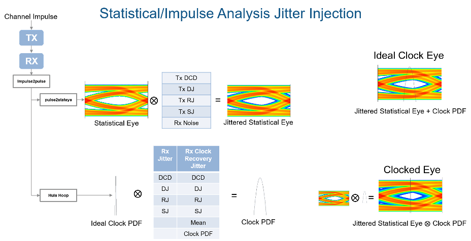
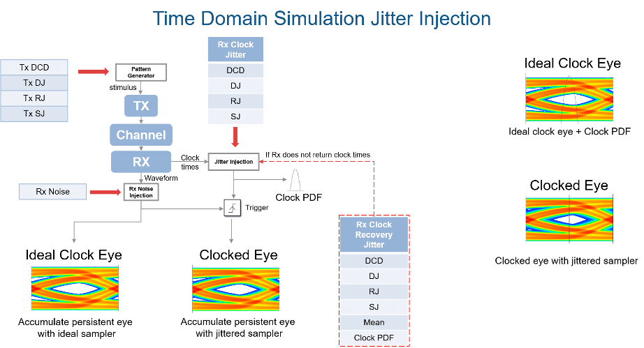
The expected simulation results vary depending on the type of jitter, injection site (transmitter or receiver), and analysis domain (statistical or time-domain). The SerDes Designer app only supports statistical or impulse-based analysis. To perform time-domain analysis, you must export the model to Simulink. The different types of jitter are injected into transmitter and receiver sites according to the IBIS-AMI specifications:
| Normal Mode | Statistical Analysis | Time Domain Analysis |
|---|---|---|
| Transmitter jitter | Convolved with eye | Injected in stimulus |
| Receiver jitter | Convolved with clock PDF (probability density function) | Injected in clock times |
| Clock recovery jitter | Convolved with clock PDF | Injected in clock times if receiver does not return clock times |