Select Slices of Input Data for SerDes System Blocks
This example uses how to select a family of input data from multiple available input data families using the Slice Select parameter of the CTLE and Saturating Amplifier blocks in the SerDes Toolbox™. You can use a single AMI parameter to synchronize the selection of input data between the two blocks.
Background
Many CTLE implementations consist of hundreds, or even thousands of equalization configurations. You may want to group several of these configurations together for various reasons, such as:
You need different groups of settings for different channel protocols. For example, PCIe, UCIe, or USB all may require different settings.
You need different settings to model process variation.
You need different settings based on the speed of operation of the system.
You need to vary the available settings based on a combination of other control settings.
In addition, the selection criteria may be common across multiple blocks. For example multiple CTLE blocks that use a common set of control parameters, or a CTLE block followed by a Saturating Amplifier block that will vary together over process.
By using a 3-D matrix to store all these values, the Slice Select input to the CTLE and Saturating Amplifier blocks allows you to index these parameters. You can then select a subset of parameter values suitable for your application.
Model Setup in SerDes Designer App
Slice Select is only used on the CTLE and Saturating Amplifier (SatAmp) data path equalization blocks, so the first part of this example sets up both these blocks using the SerDes Designer app. Launch the app with the following command:
>> serdesDesigner
Configuration Setup
Keep the default values in the Configuration panel:
Set the Symbol Time to
100ps(10GHz).Set the Modulation to
NRZ.Set the Signaling to
Differential.
Tx Model Setup
The CTLE and Saturating Amplifier blocks are typically only used in a Rx model, so we will not touch the Tx model in this example. Keep the default settings for the AnalogOut model.
Analog Channel Setup
Verify the Channel loss is set to 8 dB and the Differential impedance is set to 100 ohms.
Set the Target Frequency to
5GHz, which is the Nyquist frequency for 10 GHz.
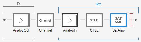
Rx Model Setup
Keep the default settings for the AnalogIn model, then add a CTLE and SatAmp block to the Rx.
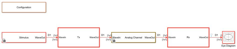
The SerDes system should look like this:
Add Family of GPZ Values to CTLE
To demonstrate using slice select to choose different sets of CTLE GPZ values, three sets of GPZ arrays are included in this example based on the PCIe values used in the example PCIe6 Transmitter/Receiver IBIS-AMI Model. These three arrays are intended to model the CTLE at 3 different process nodes:
gpz_typuses aDCgainof 5dB to 15dBgpz_slowuses aDCgainof 4dB to 14dBgpz_fastuses aDCgainof 6dB to 16dB
Begin by extracting the three arrays included with this example:
load('slice_select_gpz.mat')
Next, combine the 3 slices into a single 3D matrix by using the CombineSlices function:
gpz_all = serdes.CTLE.CombineSlices({gpz_typ, gpz_slow, gpz_fast});
gpz_all should now be a 11x8x3 matrix.
Finally, point the CTLE to the newly created matrix by setting the Specification to GPZ Matrix, and entering gpz_all for the Gain pole zero matrix value.
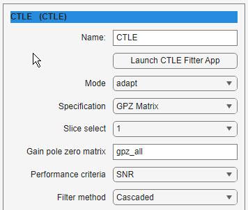
You should now see that 3 values, 0, 1 and 2, are available under the Slice select drop-down menu.
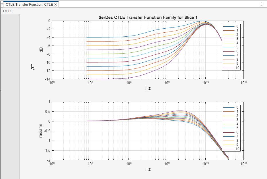
You can now plot the CTLE Transfer Function and see how the plot changes as different values of Slice select are selected.
Add Family of VinVout Values to SatAmp
To demonstrate using slice select to choose different sets of Saturation Amplifier VinVout values, three sets of VinVout arrays were generated based on the default VinVout values. These three arrays are intended to model the SatAmp at 3 different process nodes.
sat_typuses the default VinVout values directlysat_slowuses the default VinVout values multiplied by 0.9sat_fastuses the default VinVout values multiplied by 1.1
Begin by extracting the three arrays included with this example:
load('slice_select_sat.mat')
Next, combine the 3 slices into a single 3D matrix by using the CombineSlices function:
sat_all = serdes.SaturatingAmplifier.CombineSlices({sat_typ, sat_slow, sat_fast});
sat_all should now be a 11x2x3 matrix.
Finally, point the SatAmp to the newly created matrix by setting the Specification to VinVout, and entering sat_all for the VinVout matrix value.
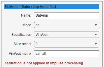
Note: Since the Saturating Amplifier is not used in impulse processing, changing the Slice Select value here will have no impact on the simulation results in SerDes Designer.
Export SerDes System to Simulink
Save and then click the Export button to export the configuration to Simulink®, where you will customize the CTLE and SatAmp blocks to use a common parameter to synchronize the value of Slice Select across the two blocks.
Note: You should get a pop-up dialog box letting you know that the base workspace variables used by the model (gpz_all and sat_all) have been copied to the model workspace in the Simulink model. This means that the Simulink model is not dependent on the parameters in the base workspace and those parameters will be saved inside the Simulink model moving forward.
Model Setup in Simulink
The second part of this example takes the SerDes system exported by the SerDes Designer app and customizes it in Simulink.
Review Simulink Model Setup
This Simulink SerDes system contains the standard configuration: Stimulus, Configuration, Analog Channel, Tx, and Rx blocks, with all values carried over from the SerDes Designer app. Review each of these blocks to verify the setup is as expected.
View SatAmp VinVout Curves
Now that you are in Simulink, the SatAmp has the ability to plot the VinVout curves. To view the curves with different values of Slice Select, double-click on the SatAmp block and select Visualize Response.
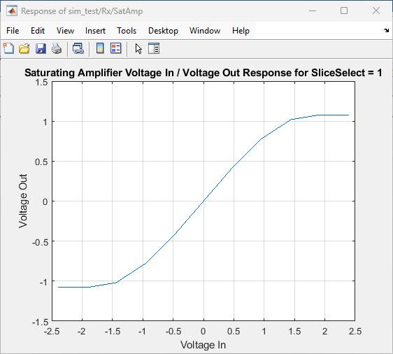
You can change the value of Slice select, then click on the Visualize Response button again to update the figure and see how the VinVout plot changes.
Create Custom Control for Slice Select
While the Rx model is now ready to be used in simulations, since both the CTLE and the SatAmp blocks use a separate slice select parameter to select the correct values for each process corner, they must each be set individually. A more user-friendly approach would be to link these two parameters together so that the user would only need to set the slice select value in one place. There are multiple ways to accomplish this:
Replace the SatAmpParameter.SliceSelect Constant block in the SatAmp block with a copy of the CTLEParameter.SliceSelect Constant block. This allows the CTLE SliceSelect parameter to control both the CTLE and SatAmp slice selects at the same time.
Put both the CTLE and SaturatingAmplifier system objects inside a Pass Through block, then create a new common AMI parameter control for both slice select inputs.
Create a new AMI parameter for the CTLE called Process, then use this AMI parameter to control both the CTLE and SatAmp slice selects at the same time. This is shown below.
This example creates a new AMI parameter since a single Process parameter is more intuitive.
Add New AMI Parameter
Open the IBIS-AMI Manager from the Configuration Block. On the AMI-Rx tab, highlight CTLE and select Add Parameter... to add a new AMI parameter. In the Add/Edit AMI Parameter dialog box:
Set the Parameter Name to:
ProcessSet Description to:
Process Corner for CTLE and Saturating Amplifier operation.Set Usage to:
InSet Type to:
IntegerSet Format to:
ListSet Default to:
0Set List values to:
[0 1 2]Set List_Tip values to:
["Typical" "Slow" "Fast"]Set the Current value to:
Typical
Press OK to add the new parameter to the CTLE.
Hide Slice Select
Since you are replacing the Slice Select AMI Parameters with the new Process AMI Parameter, you need to hide the SliceSelect parameters so they do not show up in the .ami file and are not visible to the end user.
On the AMI-Rx tab of the IBIS-AMI Manager, edit the CTLE SliceSelect parameter and check the box for Hidden and press OK. In the Rx AMI tree, you should now see a ^ character after SliceSelect to show that it has been marked as hidden.
Repeat this process for the SatAmp SliceSelect parameter.
Connect the New AMI Parameter to Each Block
A new Constant block named CTLEParameter.Process was automatically added to the CTLE when the Process parameter was added. Look under the mask of the CTLE block, delete the CTLESliceSelect Constant block, then connect the new Process constant block to the SliceSelect input on the CTLE block.
Next, copy the CTLE Process constant block, look under the mask of the SatAmp block, and paste the Process block. After deleting the SatAmpSliceSelect Constant block, connect the new Process constant block to the SliceSelect input on the SatAmp block.
Run Refresh Init
Run Refresh Init on the Rx block to automatically connect the new Process parameter to the CTLE Slice Select. You can see that the Custom user code area has been updated as follows:
%% BEGIN: Custom user code area (retained when 'Refresh Init' button is pressed)
CTLEInit.SliceSelect = CTLEParameter.Process; % User added AMI parameter from SerDes IBIS-AMI Manager
CTLEParameter.SliceSelect; % Disconnected default AMI parameter
SatAmpParameter.SliceSelect; % Disconnected default AMI parameter
% END: Custom user code area (retained when 'Refresh Init' button is pressed)
Note that since the SatAmp block is not used in Init, the new Process parameter does not need to be connected to the SatAmp.
Test the Model
Run the simulation and check that there are no errors or warnings.
You can verify proper operation by logging the input values for ConfigSelect and SliceSelect on the CTLE. You should see that as you change the value of Process and re-run the simulation, that the ConfigSelect value changes.
Generate IBIS-AMI Models
The final part of this example takes the customized Simulink model and generates IBIS-AMI compliant model executables, IBIS and AMI files for the Slice Select-enabled receiver.
Export Models
Open the SerDes IBIS-AMI Manager and select the Export tab. On the Export tab:
Keep the Tx model name as
serdes_txsince it is unmodifiedUpdate the Rx model name to
sliceselect_rxNote that the Tx and Rx corner percentage is set to
10. This will scale the min/max analog model corner values by +/-10%Verify that Dual model is selected for both the Tx and Rx AMI Model Settings. This will create a model executable that supports both statistical (Init) and time domain (GetWave) analysis.
Set the Rx model Bits to ignore value to
1000to allow enough time for the external clock waveform to settle during time domain simulationsSet Models to export to
Both Tx and RxSet the IBIS file name to be
sliceselect.ibsPress the Export button to generate models in the Target directory
Test Generated IBIS-AMI Model Executables
The Slice Select capable IBIS-AMI models are now complete and ready to be tested in any industry standard AMI model simulator such as Signal Integrity Toolbox™.
See Also
CTLE | serdes.CTLE | SaturatingAmplifier | serdes.SaturatingAmplifier