Using Signal Integrity Toolbox Analog Channels in SerDes Toolbox
SerDes Toolbox™ has a variety of channel modeling options such as a loss-based channel, user provided impulse response matrix, or importing an s-parameter. To gain more channel modeling flexibility including via models, w-lines, concatenating s-parameters, and full IBIS analog model support, Signal Integrity Toolbox™ is the best choice. With access to Signal Integrity Toolbox project data from the MATLAB® command window, you can combine the best abilities for both toolboxes for ultimate flexibility.
In this example, you will learn how to create and import channels from a Signal Integrity Toolbox project to a SerDes Toolbox Simulink® model for use in simulation.
Create Signal Integrity Toolbox Project with Coupled Channel
To start, create a Signal Integrity Toolbox project to pull channels from. For this example, a Serial Link Designer project is created by starting the Serial Link Designer app, creating a new project, and then adding a single sheet. The identical steps and code below will also work for Parallel Link Designer projects.
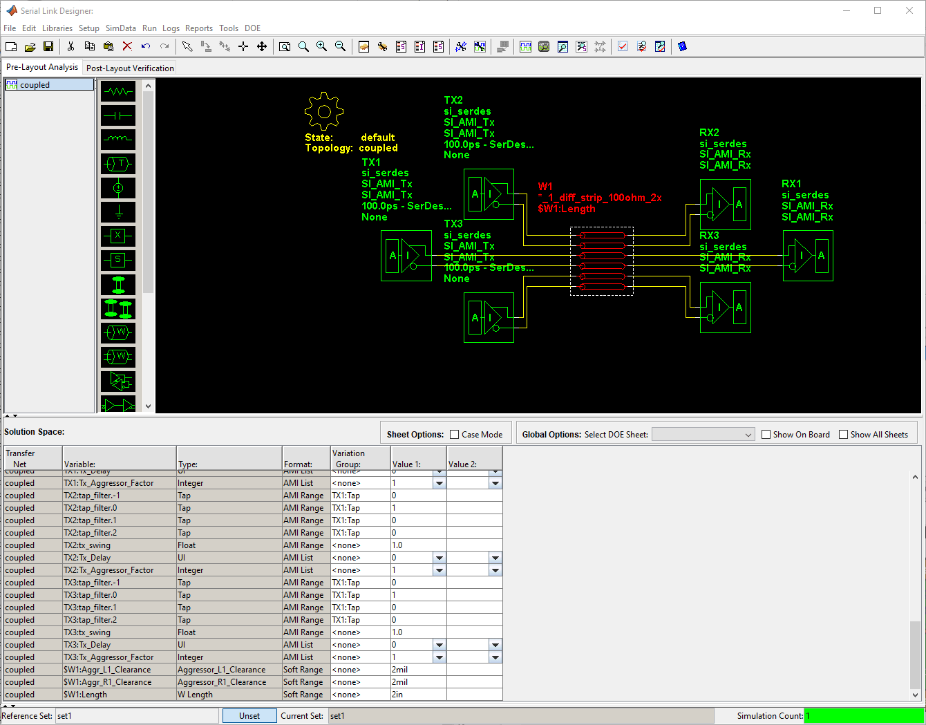
The newly added sheet is named 'coupled' and is setup with a coupled w-line (1 victim and 2 aggressors). The sheet uses the default built-in Signal Integrity Toolbox IBIS-AMI models for the victim and aggressor Tx/Rx.

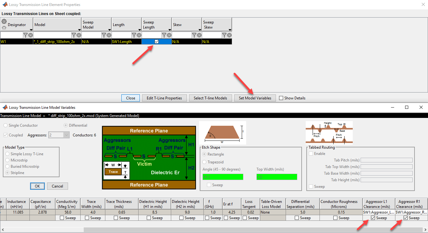
The w-line is set with sweeping enabled for both length and aggressor separation. Access the properties dialog by double clicking on the w-line.

A project with the above preconfigured options is attached to this example as a zip file and can be unzipped with the following command.
unzip SIXtalkChannel.zipSimulink Project
Create the sip object from the MATLAB command line. Access the sheet and set the w-line length to be swept from 2 to 10 inches and the aggressor separation from 2 to 10 mils. Now run simulations to create the impulse responses and other useful metrics/waveforms.
sip = SignalIntegrityProject('SIXtalkChannel'); % Use argument 'opendesigner=true' to see the GUI while running scripts
sheetNames = [sip.Sheets.Name];
coupledSheet = sip.Sheets(matches(sheetNames,"coupled"));
coupledSheet.SolutionSpace.updateSolutionSpace("$W1:Length",string(2:4:10)); % Inches
coupledSheet.SolutionSpace.updateSolutionSpace("$W1:Aggr_L1_Clearance",string(2:4:10)); % Mils
coupledSheet.SolutionSpace.updateSolutionSpace("$W1:Aggr_R1_Clearance",string(2:4:10)); % Mils
sip.run;
Create Simple SerDes Toolbox Simulink Model
Open a SerDes Toolbox model. For this example, a simple model has been put together in the script 'simpleSerDesModel.m' which will export to Simulink a Tx with a FFE and Rx with a CTLE and DFECDR.
simpleSerDesModel;
Retrieve, Format, and Save Channels in SerDes Simulink Model
Using a function (getSignalIntegrityChannels.m) provided in the example directory, retrieve the impulse responses from the Signal Integrity Toolbox sheet for each w-line length and aggressor separation. For ease of access in the SerDes Toolbox Simulink model, the impulse responses are placed in the Simulink model workspace. If no Simulink model is available, the impulses are placed in the MATLAB base workspace. The function also supports retrieving impulses from multiple Signal Integrity Toolbox sheets if present in the project.
channelsAdded = getSignalIntegrityChannels(sip);
Configure Analog Channel Block and Simulate
Set the SerDes Analog Channel block to type Impulse Response and set the Impulse to one of the channels from the Signal Integrity Toolbox project. Start with the less coupled channel (less crosstalk).
mdl = bdroot;
if ~isempty(mdl)
    analogChannelBlock = find_system(bdroot,'Name', 'Analog Channel');
    if ~isempty(analogChannelBlock)
        analogChannelBlock = analogChannelBlock{1};
        set_param(analogChannelBlock,'ChannelType','Impulse Response');
        set_param(analogChannelBlock,'ImpulseResponse',channelsAdded{contains(channelsAdded,'10_10_10')}); % Coupled 10" channel with 10mil separation
        set_param(analogChannelBlock,'IncludeCrosstalkCheckBox','on');
    end
end
Now run the Simulink model and record the results.
sim(mdl)
ans =
  Simulink.SimulationOutput:

                logsout: [1x1 Simulink.SimulationData.Dataset]
                   tout: [320001x1 double]

     SimulationMetadata: [1x1 Simulink.SimulationMetadata]
           ErrorMessage: [0x0 char]
mws = get_param(mdl, 'ModelWorkspace');
results = mws.getVariable('SerDesResults');
results.TimeDomain.summary
ans=8×2 cell array
    {'Eye Height (V)' }    {[    0.4090]}
    {'Eye Width (ps)' }    {[   85.9398]}
    {'Eye Area (V*ps)'}    {[   21.7241]}
    {'COM'            }    {[   17.2879]}
    {'VEC'            }    {[    1.2763]}
    {'Minimum BER'    }    {[5.2632e-05]}
    {'Ignore Symbols' }    {[      1000]}
    {'Total Symbols'  }    {[     20000]}
Now set to the channel with more coupling (more crosstalk) and run simulation again
mdl = bdroot;
if ~isempty(mdl)
    analogChannelBlock = find_system(bdroot,'Name', 'Analog Channel');
    if ~isempty(analogChannelBlock)
        analogChannelBlock = analogChannelBlock{1};
        set_param(analogChannelBlock,'ChannelType','Impulse Response');
        set_param(analogChannelBlock,'ImpulseResponse',channelsAdded{contains(channelsAdded,'2_2_10')}); % Coupled 10" channel with 2mil separation
        set_param(analogChannelBlock,'IncludeCrosstalkCheckBox','on');
    end
end
sim(mdl)

![Figure Init Statistical and Time Domain Analysis Results contains 4 axes objects and other objects of type uipanel. Axes object 1 with title Pulse Response, xlabel [s], ylabel [V] contains 6 objects of type line. These objects represent Unequalized primary, Unequalized agr1, Unequalized agr2, Equalized primary, Equalized agr1, Equalized agr2. Axes object 2 with title Waveform Derived from Pulse Response, xlabel [s], ylabel [V] contains 6 objects of type line. These objects represent Unequalized primary, Unequalized agr1, Unequalized agr2, Equalized primary, Equalized agr1, Equalized agr2. Axes object 3 with title Statistical Eye, xlabel [ps], ylabel [V] contains 3 objects of type image, line. Axes object 4 with title Time Domain Eye, xlabel [ps], ylabel [V] contains 3 objects of type image, line.](../../examples/si/win64/UsingSignalIntegrityToolboxAnalogChannelsInSerDesToolboxExample_04.png)
ans =
  Simulink.SimulationOutput:

                logsout: [1x1 Simulink.SimulationData.Dataset]
                   tout: [320001x1 double]

     SimulationMetadata: [1x1 Simulink.SimulationMetadata]
           ErrorMessage: [0x0 char]
mws = get_param(mdl, 'ModelWorkspace');
results = mws.getVariable('SerDesResults');
results.TimeDomain.summary
ans=8×2 cell array
    {'Eye Height (V)' }    {[    0.3222]}
    {'Eye Width (ps)' }    {[   80.0862]}
    {'Eye Area (V*ps)'}    {[   16.1863]}
    {'COM'            }    {[   12.4176]}
    {'VEC'            }    {[    2.3768]}
    {'Minimum BER'    }    {[5.2632e-05]}
    {'Ignore Symbols' }    {[      1000]}
    {'Total Symbols'  }    {[     20000]}
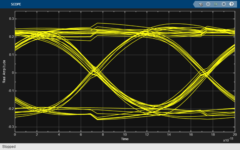
Notice that the eye height and eye width were reduced with higher crosstalk. Continue to select any of the channels that were saved in the model workspace to explore other crosstalk configurations.