Get Started with Serial Link Designer
Designers embarking on projects with 3+ Gbps serial links are confronted with a confusing array of tools, techniques and terminology. Traditional time-domain simulation using SPICE alone does not provide an adequate estimate of the Bit Error Rate (BER) of a serial link, which is the key metric used to assess reliability.
When simple transistor level models are used for the active devices, compute time considerations typically limit simulations to a few thousand bits. When more complex models are used that model transmitter and receiver equalization, compute time increases, limiting practical simulations to hundreds of bits at best.
In high-speed serial links there is processing before the I/O stage (transmit equalization) and after the input buffer (receive equalization and clock recovery). The signal of importance is not at the pin or die pad of the receiver, it is the decision point of the receiver, an internal point that is after the receive equalization. In addition, the clock recovery circuitry in the receiver must be taken into account to estimate BER accurately.
In order to estimate BER for such a receiver the equalization and clock recovery need to be modeled, and simulators need to access the waveform at the decision point. The IBIS-AMI (Algorithmic Modeling Interface) standard was developed to provide this in a way that preserves vendor IP and allows inter-operability between EDA tools and vendor models. The IBIS-AMI standard defines an interface to an algorithmic model that is an executable program. The analog portion of a model uses the existing IBIS IV and VT curves. The algorithmic model is used to model equalization, clock recovery and device optimization.
There are three main challenges to estimating BER:
ISI (Inter-Symbol Interference) — looked at in the time domain, more bits interact with each other, so more combinations of bits need to be analyzed. Looked at in the frequency domain, a wider bandwidth with more loss variation means equalization is required.
Clock to data timing (at the receiver decision point) — has less margin, so timing perturbations must be carefully accounted for and analyzed.
Crosstalk — increases with frequency.
The Serial Link Designer app uses a combination of statistical and time domain techniques to estimate the BER of a serial link in a fraction of the time it would take using transient non-linear simulation. The app also uses specific project settings and libraries to organize the simulations.
Statistical Analysis of Linear Time Invariant System
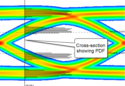
Statistical analysis uses a recursive convolution engine to calculate the eye diagram PDF (probability distribution function) from the pulse response of an LTI (linear time invariant) system. This is called a statistical eye.

The statistical eye shows the average effect of all messages of a given length. This is a very fast way to explore a wide range of design options. The major factors affecting performance are handled in the following way:
Inter-Symbol Interference — The effects of inter-symbol interference are reflected directly in the PDF of the eye diagram. This is a very accurate and efficient way to calculate the inter-symbol interference due to all possible combinations of bits, even for very long message lengths.
Clock to Data Timing — The PDF of the clock can be combined with the PDF of the eye diagram to produce a very rigorous BER estimate.
Crosstalk — The PDF of the crosstalk can be convolved with the PDF of the eye diagram to produce a composite PDF which accurately and completely reflects the effects of crosstalk. When combined with the clock to data timing mentioned above, the resulting BER estimate is both rigorous and complete.
A convolution engine calculates the statistical eye for a signal by sequentially adding in the contribution of each successive bit offset. For each bit offset, the pulse response for that offset is convolved with the statistical eye that has been accumulated so far. As a result, only N convolutions are required to compute the statistical eye for all messages of length N+1. To achieve the same result in a time domain simulation would require on the order of 2N bits. Thus, whereas N = 20 is practical in the time domain, N=500 is practical with a convolution engine.
Peak distortion analysis can be used to derive the worst case data pattern for the system.
Time Domain Analysis of Linear Time Invariant System
Time Domain analysis is a semi-analytic analysis method in which up to a few million bits of the desired signal are simulated in the time domain, and then the effect of the noise, crosstalk and clock phase noise is estimated using statistical techniques. This has the advantage of allowing time variant and nonlinear effects to be studied, such as pattern dependence in the clock recovery and equalization control loops to be studied while maintaining the efficiency and dynamic range of statistical calculations. The ability to simulate specific data patterns also makes this approach useful for correlating with measured data or determining worst case performance. The major factors affecting performance are handled in the following way:
Inter-Symbol Interference — The eye diagram accumulated over the course of the time domain simulation is either a random or deterministic sampling of the inter-symbol interference. While this is sufficient if the inter-symbol interference only occurs over short message lengths, it is difficult to obtain a representative sample for long message lengths.
Clock to Data Timing — The same conditional probability technique that is used with the statistical eye from a convolution engine can be used with the eye diagram from a time domain simulation to produce a reasonably accurate BER estimate. This estimate will tend to vary by a factor of ten or more, however, unless the number of symbols in the simulation is quite large.
Crosstalk — Although crosstalk could be included explicitly in the time domain simulation, this would be used primarily to determine the effects of crosstalk on the clock recovery and equalization control loops. For BER estimation, it's much more effective to include the crosstalk in the statistical part of the analysis.
Organization of Simulations
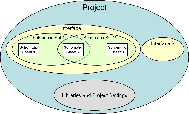
The Serial Link Designer app consists of four major project elements:
Project — A project typically represents a full system that may include one or more boards and one or more bus types. For example, a system may have XAUI and PCIe serial links, or serial links and parallel bus memory channels.
Interface — An interface is one subset of the system design, for example the XAUI serial channel or a parallel bus memory. A project can have one or more interfaces. All work in the Serial Link Designer app is performed in an interface of a project.
Schematic Sheet — A schematic sheet is a graphical representation of the serial channel, captured using elements such as designators, transmission lines, s-parameters, vias and more. A schematic sheet is always a part of a schematic set.
Schematic Set — A schematic set is a collection of schematic sheets in an interface. Each schematic set may represent a different configuration of the Interface. In the Serial Link Designer app an interface can have one or more schematic sets.

The app also uses some specific terms to define certain elements that are useful:
Transfer net — Each signal type in an interface is called a transfer net, and consists of the drivers, receivers, electrical conductors and passive components involved in transmitting that signal type. There may be multiple instances of a transfer net in an interface (example: data lines) or there could be a single instance (example: clock).
Transfer nets are common to both pre-layout analysis and post-layout verification. In pre-layout analysis, each sheet has an associated transfer net with the same name as the sheet. In post-layout verification, extended nets are assigned to transfer nets.
Solution space — Variations of parameters such as voltage, temperature, or process for each transfer net are organized into a solution space.
Designator — Within a transfer net, drivers and receivers are referred to as designators. In other words, a designator is either a starting point or an end point for a transfer net and is therefore a point where timing analysis is to be performed.
Libraries
The Serial Link Designer app comes with libraries of technology and generic models. The technology and generic library models can be assigned to schematic designators. The library elements include I/O buffer models, transmission line models, IBIS models, SPICE package models, and S-Parameter files. By default, new projects and interfaces automatically reference the project’s local library as well as the installation library.
See Also
Serial Link Designer | Signal Integrity Viewer