Filter Mixing Products
This example shows you how to:
Configure a RF Blockset Outport block to probe multiple carrier frequencies simultaneously.
Model an analog filter in the RF Blockset™ environment using RF Blockset Capacitor and Inductor blocks.

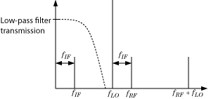
The preceding figure illustrates low-pass filtering of a low-side injection system. Mixing fRF and fLO produces signals on the carriers fIF = fRF – fLO and fRF + fLO. Adding a low-pass filter to the model reduces the power present in the high-frequency signal.
Probe Multiple RF Carriers
To begin, open the model that you created in the Model an RF Mixer example.

The RF Blockset environment specifies the carriers fRF – fLO, fRF, fLO, and fRF + fLO, but the RF Blockset Outport block probes only the carrier fRF – fLO. Examine the carriers fRF – fLO and fRF + fLO by changing the model according to the following workflow:
From Simulink Commonly Used Blocks library, add a Demux block to your model.
In the Scope block dialog box, click the Parameters button, then set Number of Axes to
2. In the Outport block dialog box, set *Carrier frequencies to[RFCarrier – LOFrequency, RFCarrier + LOFrequency].

Run to run the model and to view the results of the simulation, double-click the scope.

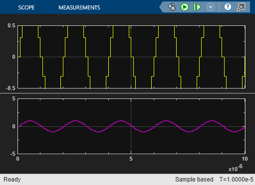
The first set of axes displays the modulation of specified carrier fIF = fRF – fLO. This carrier appears on the first set of axes because the Carrier frequencies parameter of the outport specifies it first. The second set of axes displays the modulation at fRF + fLO. The modulation of the upper mixing product has the same amplitude as the modulation of the downconverted signal.
Model RF Filter
To begin, open the model that you created in the Probe Multiple RF Carriers section.

This configuration models a third-order low-pass Butterworth filter with a cutoff frequency of 1 rad/ns, or about 0.159 GHz. The high-frequency mixing product is in the stopband of the filter. The low-frequency product is in the passband. You can also use an LC Ladder block to model this filter.
Select Run to simulate Filtering of RF Signals.

The filter attenuates the high-frequency signal at fRF + fLO and transmits the signal at fRF – fLO with minimal loss.
Improve Performance by Reducing Total Simulation Frequencies
The models in the preceding examples use the Automatically select fundamental tones and harmonic order setting in the Configuration block. This setting sacrifices performance for compatibility by guaranteeing that every specified Carrier Frequency parameter appears in the set of RF Blockset simulation frequencies. The performance of the ex_simrf_tut_filter_model can be improved by reducing the size of the set of simulation frequencies, as measured by the Total simulation frequencies value displayed in the Configuration block dialog.
To enhance performance of the ex_simrf_tut_filter_model, follow the procedure below.
Open and simulate the
ex_simrf_tut_filter_model.Double-click the Configuration block to open the block dialog box. Note that the block dialog displays a Total simulation frequencies value of
121. This value indicates that the environment is running 121 separate simulations.Clear the Automatically select fundamental tones and harmonic order check box.
Set Fundamental tones to
[RFCarrier, LOFrequency]. This step is not strictly necessary, but setting these values clarifies the meaning of the parameters. Because the mixer has fRF and fLO at its input ports, all signals at the output of the mixer have carrier frequencies that are linear combinations of these fundamental tones.Set Harmonic order to
1. The frequencies fRF + fLO and fRF – fLO are the only output carriers of interest. Modeling signals at a higher harmonic order than one is not necessary for this system.Click Apply. Note that the block dialog displays a Total simulation frequencies value of 9.
Simulate the model.
The result of the simulation has not changed because every frequency of importance appears in the new set of simulation frequencies. However, this procedure reduces overall compatibility. If you make modifications to the model, such as adding nonlinear amplification, the resulting signals of interest may not appear in the set of simulation frequencies. You can restore compatibility by restoring the Automatically select fundamental tones and harmonic order check box to its default.