Create Custom RF Blockset Models
This example shows how to write your own RF Blockset™ Circuit Envelope model in Simscape® language for complex baseband simulation. An RF Circuit Envelope complex baseband signal resides on a carrier with specified frequency. This baseband signal will modulate with other signals when the system is nonlinear. The example nonlinearity is implemented with a Simscape Component block and includes a Simscape ssc-file to describe the nonlinear voltage polynomial.
System Architecture
The system consists of:
An input voltage signal, linearly increasing in time and generated with a Simulink Ramp block.
An RF Blockset Inport block to specify the
Carrier frequencies(Input_Freq) of the input voltage signal. This setup allows observation of the system nonlinear behavior for different input settings.A custom nonlinear voltage amplifier (polynomial voltage controlled voltage source), modeled with a Simscape Component block. The device equations are written in passband (time) domain and assume instantaneous voltage V(t) and current I(t) values. These equations are interpreted by RF Blockset envelope solver in both passband and baseband domains (zero and nonzero carrier frequencies).
An Outport block to specify output
Carrier frequencies(Output_Freqs). The output carrier frequencies are higher order harmonics (integer multiples) of the Inport frequency resulting from the amplifier nonlinearity.A Scope to display the magnitudes of the output voltages at Output_Freqs frequencies as specified in the Outport block.
Load resistors and ground nodes needed to make the circuit electrically sound. By construction, the resistor values do not affect the output voltage.
A Configuration block to control the system carrier frequencies required for accurate simulation and other simulation properties.
model = 'simrfV2_custom_polynomial';
open_system(model);

Examine Model
Double-click the "Custom Nonlinearity" block or type open_system([model '/Custom Nonlinearity']) in the command window to open the Custom Nonlinearity block mask.

The file simrfV2_custom_vcvs.ssc describes the custom device. View the source code by clicking the block mask "Source code" link or typing edit simrfV2_custom_vcvs at the command prompt.
Copy the file simrfV2_custom_vcvs.ssc to a directory where you have write permission to rename and modify the file. Click the block mask "Choose source" button to replace the current device implementation with yours. Use the mask Help button for additional information.
The above method uses the Simscape Component block from the Simscape Utilities library to avoid the library build process. For more information, see Custom Components.
Run Model Using Default Settings
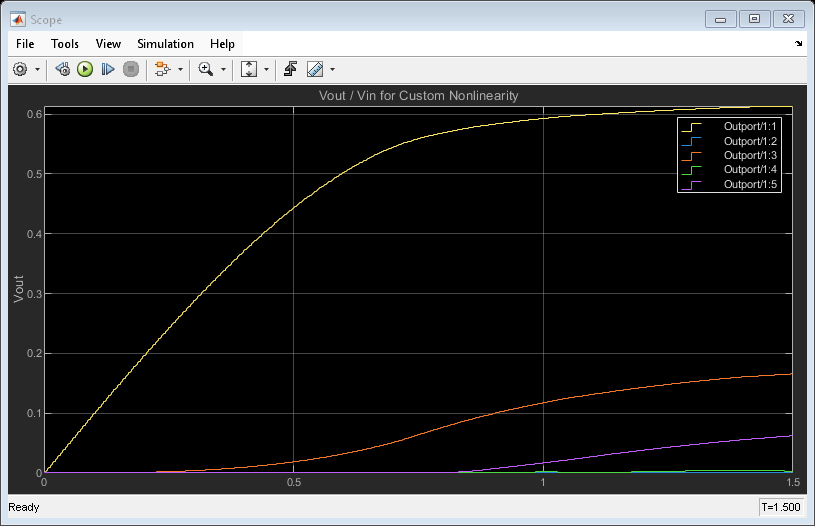
For this example, default input and output frequencies are set to 0 and the result is a passband simulation. The input voltage magnitude is linearly increasing in time, Vin(t) = t, and the custom nonlinearity relationship Vout(Vin) is shown in the scope.
The model is simulated after entering the following into the command window
sim(model);

Observe the response produced by the cubic polynomial specified in the 'Custom Nonlinearity' model. The saturated output voltage occurs at time 0.7 seconds and corresponds to the input voltage of 0.7 V.
Run Model with Non-zero Input Carrier
Set the input carrier frequency to 1 GHz and the output frequencies to the first five harmonics of the input. For non-zero carrier input frequency, RF Blockset interprets the input as a complex baseband signal. This complex baseband signal only has an in-phase part specified.
Type the following at the Command Prompt:
Input_Freq = 1e9;
Output_Freqs = (1:5)*Input_Freq;
sim(model);

Since the coefficients c0 and c2 are zero, the output has only odd harmonics (1 GHz, 3 GHz and 5 GHz) until the output voltage reaches saturation. Other harmonics are introduced for large values of input voltage because of saturation effects.
The relationship between the output curves, polynomial coefficients and IP2/IP3/P1db coefficients is well-studied in the literature [1,2].
Conclusion
An RF Blockset model can be written as a time-domain electrical model in the Simscape language. The model equation can include many types of characteristics, such as derivatives and history (not shown in this example). As with any other model description language, the modeler is responsible for the validity of the model:
The equations are consistent.
The equations cannot be degenerate, unstable, or discontinuous. Avoid negative resistances, large nonlinearities and sharp transitions.
The model does not produce convergence errors during the simulation.
Bibliography
Kundert, Ken. "Accurate and Rapid Measurement of IP2 and IP3." The Designers Guide Community, Version 1b, May 22, 2002.
Chen, Jesse. "Modeling RF systems." The Designers Guide Community, Version 1, 6 March 2005.
bdclose(model)
See Also
Configuration | Inport | Outport