Modeling and Simulation of MIMO RF Receiver Including Beamforming
This example shows how to model a MIMO RF receiver with a baseband beamforming algorithm. It considers antenna coupling effects and RF imperfections. The simulation of the system-level model includes the RF receiver baseband beamforming algorithms, RF imperfections, and the antenna array radiation pattern.
In the following sections, you will see more details about the transmitter, receiver, and beamforming algorithm.
Transmitter and Channel
The transmitter and channel models are ideal.
The transmitter constructs a simple modulated signal transmitted using a single antenna.
The channel model introduces path loss attenuation and adds an interfering narrowband signal with power level similar to the desired signal.
The model assumes that transmitter and receiver are positioned on the same plane. You can change the angle of arrival of the desired transmitted signal and of the interfering signal by turning the dials on the Simulink diagram.
An angle of 90 degrees indicates that the transmitter is in front of the receiver, where the main lobe of the antenna array radiation pattern is located.
An angle of 120 degrees indicates that the transmitter is 30 degrees away from the normal axis to the array, where a null of the radiation pattern is positioned.
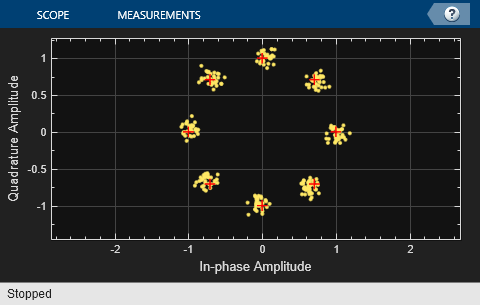
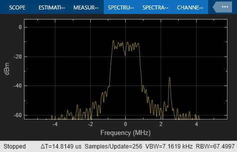
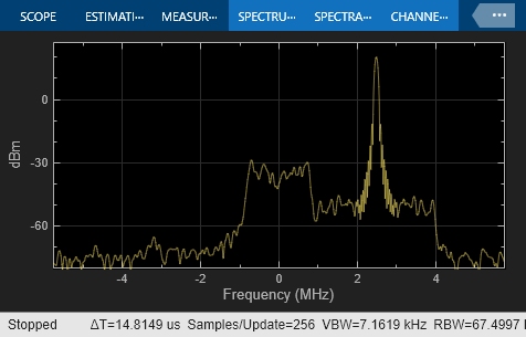
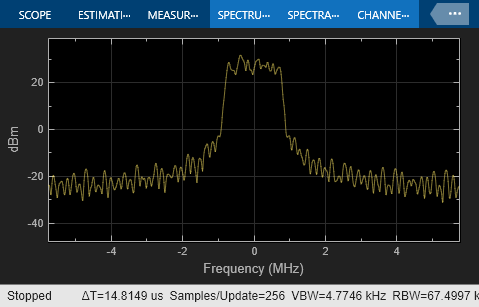
Changing the relative angle of arrival for desired and interfering signals will change the relative signal powers in the Spectrum Analyzer scope "Spectrum without Beamforming". In this case, all 8 received signals are just summed together, without applying any beamforming algorithm.

Design the Receiver Antenna Array
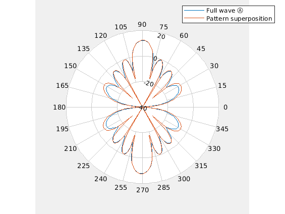
The receiver antenna array is designed using Antenna Toolbox™. The Antenna Toolbox helps you design an antenna at the desired operating frequency and verify that the pattern superposition of the isolated element is an acceptable approximation for the array simulation.
Script to design and verify the antenna array
As you can see, the antenna array consists of 8 dipole antennas resonating at 5 GHz. The comparison of the far-field radiation pattern of the array computed with full-wave analysis and pattern superposition of the isolated element shows modest differences:
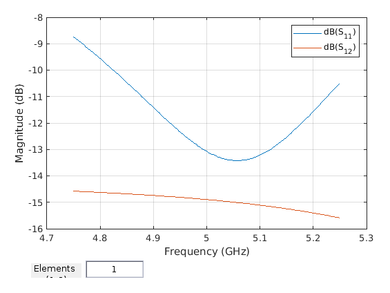
However, the S-parameters show a non-negligible leakage between adjacent antennas.
RF Receiver
The receiver model includes:
Model of receiver antenna array. The receiver antenna array is composed using 8 dipole antennas operating at 5 GHz. The array radiation pattern is modeled with Phased Array System Toolbox™ "Narrowband Rx array". The array is simulated using pattern superposition of the isolated element stored in the variable
P_antenna, computed using Antenna Toolbox and the script. You can visualize the radiation pattern by clicking the Analyze button in the sensor array tab.
Model of RF receiver. The RF receiver is composed with eight non-linear superheterodyne receivers and filters described with S-parameters. Each chain is designed with the RF Toolbox™ RF Budget Analyzer app as described in: RF Receiver Design example.
Antenna array impedance is described with the eight-port S-parameters computed using Antenna Toolbox. The S-parameters capture the loading of the antenna array on the RF receiver as well as the coupling between the antenna elements. A lumped inductance for each receiver is used to retune the respective antenna.
Eight 12-bit ADCs capturing the finite dynamic range of the data converters by modeling saturation and quantization.
DOA & Beamforming
The baseband receiver algorithm consists of four main elements in a closed feedback loop.
Root MUSIC algorithm to determine the Direction of Arrival assuming that two signals are present. The two estimated DOA angles are passed to a state machine that determines which angle produces the higher Modulation Error Ratio (MER). This state machine includes some time delay in between state transitions to avoid decision jitter.
MVDR Beamforming algorithm for the receiver to focus on the desired signal and suppress interference and noise from other directions. It uses the angle chosen by the Control Logic to maximize the MER.
Signal Conditioning and estimation of the Modulation Error Ratio. The MER is used to determine which angle to select for the beamforming algorithm.