Active Interface

Libraries:
Simscape /
Battery /
HIL
Description
The Active Interface block provides an abstracted active interface between a battery and a cell supervisory circuit. Use this block with desktop simulations and hardware-in-the-loop battery emulation hardware.
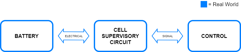
A cell supervisory circuit is an electronic circuit that connects to battery cells or parallel assemblies. You can use this circuit to normalize voltages or states-of-charge (SOC) inside a module or pack. In the real world, you implement this equipment between your battery and the battery management system (BMS) control.
In this figure, the items in blue represent real-world equipment, voltages, and currents.
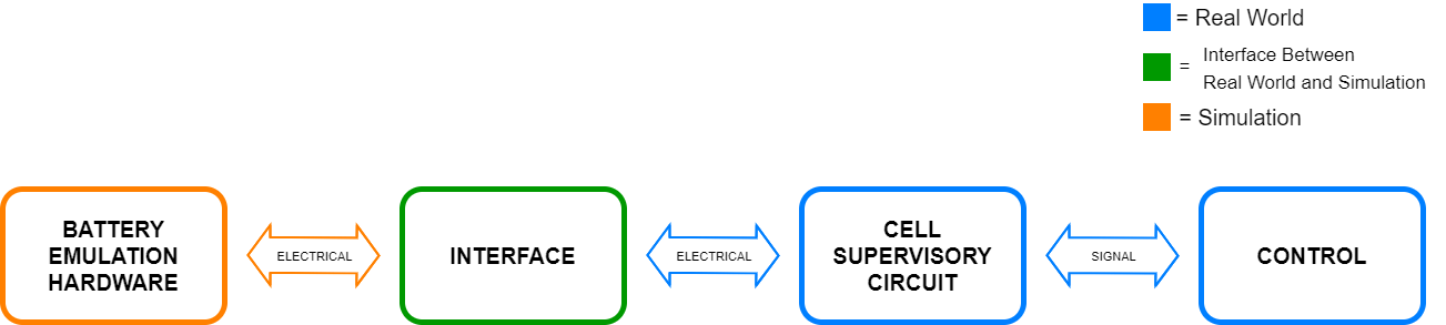
To avoid damaging your battery and to test your cell balancing algorithms under standard operational conditions and fault conditions, you can use hardware-in-the-loop battery emulation hardware. An abstracted interface facilitates connecting, setting, and configuring the passive balancing BMS to your emulated battery.
In this figure:
The blue color represents real-world equipment, voltages, and currents.
The green color represents the interface between the real-world equipment, voltages, and currents, as well as the simulated equipment, voltages, and currents.
The orange color represents the simulated equipment, voltages, and currents.
The Active Interface block provides the abstract representation of power electronic equipment without the need to model it in detail. For example, if you have a battery pack with different levels of temperature or voltage within its constituent parts, you can use this block to check if the BMS is correctly balancing your pack after a variety of operational scenarios.
If the input signal Vcsc_charge is less than the simulated battery voltage, Vbat, then:
The simulated battery is discharging.
The value at the IsCharging output port is
0(false).The Icsc_discharge input port specifies the current in the cell supervisory circuit.
The value at the Icsc output port is numerically identical to the value at the Icsc_discharge input port. This output is a measurement of the current supplied to the cell supervisory circuit.
If the input signal Vcsc_charge is greater than or equal to Vbat, then:
The simulated battery is charging.
The value at the IsCharging output port is
1(True).The Vcsc_charge input port specifies the voltage across the battery minus the voltage drop across the resistance of the cell supervisory circuit.
The block ignores the Icsc_discharge input.
The Icsc output port is a measurement of the current supplied to the cell supervisory circuit. Therefore, when the BMS is charging the battery, this current has a negative value.
SOC Optional Ports
Use the optional SOC ports of the Active Interface block to avoid implementing an SOC estimation algorithm in the BMS, to validate and verify the SOC estimation algorithm against the simulated SOC, or to represent a real-world battery.
If, in your model, the battery has an SOC output port, expose the SOC input port of this block and connect the ports appropriately. To expose the SOC input port of this block, set the Expose SOC input port parameter to
Yes.To avoid implementing an SOC estimation algorithm in the BMS or to validate and verify the SOC estimation algorithm against the simulated SOC, expose the SOC output port of this block and connect it to your BMS. To expose the SOC output port of this block, set the Expose SOC output port parameter to
Yes.To represent a real-world battery, do not expose the SOC ports of this block.
Thermal and Temperature Optional Ports
Use the optional thermal and temperature ports of the Active Interface block to represent a battery with a temperature sensor or to validate and verify the temperature estimation algorithm against the simulated temperature.
If, in your model, the battery has a temperature sensor, expose the thermal port H of this block and connect it to the thermal network. To expose the thermal port of this block, set the Thermal port parameter to
Model.To validate and verify the temperature estimation algorithm against the simulated temperature, expose both the thermal port H and the temperature measurement port T of this block and connect them to the thermal network and your BMS, respectively. To expose the temperature measurement port of this block, set the Expose temperature measurement port parameter to
Yes.If, in your model, the battery does not include thermal effects or does not have a temperature sensor, do not expose the thermal and temperature ports of this block.
Ports
Input
Output
Conserving
Parameters
Extended Capabilities
Version History
Introduced in R2022b