Model Thermal Boundary Conditions at Edges of Battery Systems
Simscape™ Battery™ allows you to expose the thermal nodes of the cells located at the surface boundaries of a battery parallel assembly or module. These thermal boundary conditions affect the battery cells at the edges or boundaries of a battery system, which then experience different thermal dynamics compared to the battery cells inside the battery assembly. By exposing the thermal nodes, you can model and analyze the heat transfer within the battery more accurately, simulate the interaction between the battery surface and the environment, study the temperature gradients across the battery cells, and integrate thermal management systems into the simulation model more easily.
This figure shows the boundaries where you can expose the vectorized or scalar thermal nodes for the battery cells:

To expose the thermal nodes at a specific surface boundary, specify the
XminThermalNodes, XmaxThermalNodes,
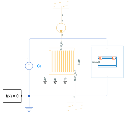
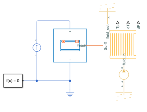
YminThermalNodes, and YmaxThermalNodes
properties of a ParallelAssembly
or Module object.
You can set these properties to:
"None"— Do not expose thermal nodes."Scalar"— Expose a lumped thermal node at the minimum or maximum axis surface boundary."Vectorized"— Expose an array of thermal nodes at the minimum or maximum axis surface boundary.
For an example on how to implement scalar and vectorized thermal boundary conditions, see Add Vectorized and Scalar Thermal Boundary Conditions to Battery Models.
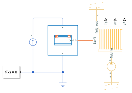
Expose Thermal Nodes at Surface Boundaries for Parallel Assemblies
The model and simulation output for a battery parallel assembly with exposed thermal nodes at a specific surface boundary depend on the surface thermal boundaries and model resolution of the parallel assembly.
This table shows the relationship between the surface thermal boundaries, the model
resolution, and the affected cells. The CellsAtXminBoundary,
CellsAtXmaxBoundary, CellsAtYminBoundary, and
CellsAtYmaxBoundary properties are read-only properties that show the
indexes of the cells at the specified minimum or maximum axis surface boundary, returned as
vectors of integers.
| Parallel Assembly Thermal Boundary | Model | Simulation Output | Layout |
|---|---|---|---|
Model Resolution: Detailed |
|
| Layout 1 6 11 16 21 26 2 7 12 17 22 27 3 8 13 18 23 28 4 9 14 19 24 29 5 10 15 20 25 30 CellsAtXminBoundary 1 6 11 16 21 26 |
Model Resolution: Detailed |
|
| CellsAtXmaxBoundary 5 10 15 20 25 30 |
Model Resolution: Detailed |
|
| CellsAtXminBoundary 1 6 11 16 21 26 CellsAtXmaxBoundary 5 10 15 20 25 30 CellsAtYminBoundary 1 2 3 4 5 CellsAtYmaxBoundary 26 27 28 29 30 |
Model Resolution: Lumped |
|
| CellsAtXminBoundary 1 6 11 16 21 26 |
Model Resolution: Detailed |
|
| Layout 1 6 11 16 21 26 2 7 12 17 22 27 3 8 13 18 23 28 4 9 14 19 24 29 5 10 15 20 25 30 CellsAtXminBoundary 1 6 11 16 21 26 |
Model Resolution: Detailed |
|
| CellsAtXmaxBoundary 5 10 15 20 25 30 |
Model Resolution: Detailed |
|
| CellsAtXminBoundary 1 6 11 16 21 26 CellsAtXmaxBoundary 5 10 15 20 25 30 CellsAtYminBoundary 1 2 3 4 5 CellsAtYmaxBoundary 26 27 28 29 30 |


Expose Thermal Nodes at Surface Boundaries for Modules
The model and simulation output for a battery module with exposed thermal nodes at a specific surface boundary depend on the surface thermal boundaries and model resolution of the module.
This table shows the relationship between the surface thermal boundaries, the model
resolution, and the affected cells. The CellsAtXminBoundary,
CellsAtXmaxBoundary, CellsAtYminBoundary, and
CellsAtYmaxBoundary properties are read-only properties that show the
indexes of the cells at the specified minimum or maximum axis surface boundary, returned as
vectors of integers.
| Module Thermal Boundary | Model and Simulation Output | Layout | |
|---|---|---|---|
Model Resolution: Detailed |
| Layout 1 5 9 13 2 6 10 14 3 7 11 15 4 8 12 16 17 21 25 29 18 22 26 30 19 23 27 31 20 24 28 32 33 37 41 45 34 38 42 46 35 39 43 47 36 40 44 48 CellsAtXminBoundary 1 5 9 13 | |
Model Resolution: Detailed |
| CellsAtXmaxBoundary 36 40 44 48 | |
Model Resolution: Detailed |
| Layout 1 5 9 13 17 21 25 29 33 37 41 45 2 6 10 14 18 22 26 30 34 38 42 46 3 7 11 15 19 23 27 31 35 39 43 47 4 8 12 16 20 24 28 32 36 40 44 48 CellsAtYminBoundary 1 2 3 4 | |
Model Resolution: Detailed |
| Layout 1 5 9 13 17 21 25 29 33 37 41 45 2 6 10 14 18 22 26 30 34 38 42 46 3 7 11 15 19 23 27 31 35 39 43 47 4 8 12 16 20 24 28 32 36 40 44 48 CellsAtYmaxBoundary 45 46 47 48 | |
Model Resolution: Detailed |
| CellsAtXminBoundary 1 5 9 13 17 21 25 29 33 37 41 45 CellsAtXmaxBoundary 4 8 12 16 20 24 28 32 36 40 44 48 CellsAtYminBoundary 1 2 3 4 CellsAtYmaxBoundary 45 46 47 48 | |