PI Controller with Integral Anti-Windup (Discrete or Continuous)
R2026bDiscrete-time or continuous-time PI control with integral anti-windup
PI Controller with Integral Anti-Windup (Discrete or Continuous) block
To add a block to a model, double-click the canvas and start typing the block name. Then, select the block from the list.
Libraries:
Simscape /
Electrical /
Control /
General Control
Description
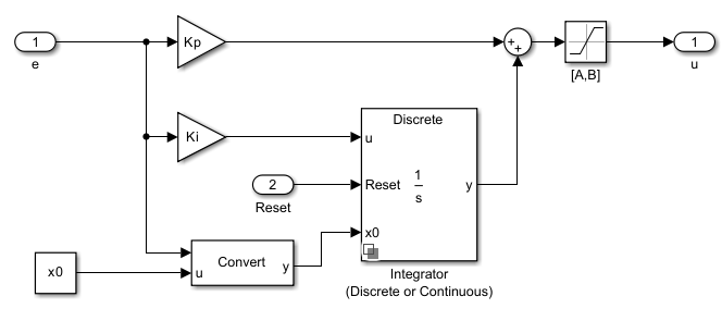
The PI Controller with Integral Anti-Windup (Discrete or Continuous) block implements discrete-time or continuous-time PI control with internal anti-windup. This figure shows the equivalent circuit for the controller with internal anti-windup.
Equations
The block calculates the control signal using the backward Euler discretization method:
where:
u is the control signal.
Kp is the proportional gain coefficient.
e is the error signal.
Ki is the integral gain coefficient.
Ts is the sampling period.
A is the lower limit for saturation.
B is the upper limit for saturation.
Examples
Energy Balance in a 48V Starter Generator
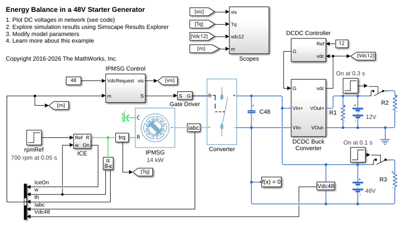
An interior permanent magnet synchronous machine (IPMSM) used as a starter/generator in a simplified 48V automotive system. The system contains a 48V electric network and a 12V electric network. The internal combustion engine (ICE) is represented by basic mechanical blocks. The IPMSM operates as a motor until the ICE reaches the idle speed and then it operates as a generator. The IPMSM supplies power to the 48V network, which contains the R3 power consumer. The 48V network supplies power to the 12V network which has two consumers: R1 and R2. The total simulation time (t) is 0.5 seconds. At t = 0.05 seconds, the ICE turns on. At t = 0.1 seconds, R3 switches on. At t = 0.3 seconds, R2 switches on and increases the load on the 12V electric network. The EM Controller subsystem includes a multi-rate PI-based cascade control structure which has an outer voltage-control loop and two inner current-control loops. The task scheduling in the Control subsystem is implemented as a Stateflow® state machine. The DCDC Controller subsystem implements a simple PI controller for the DC-DC Buck converter, which feeds the 12V network. The Scopes subsystem contains scopes that allow you to see the simulation results.
IPMSM Torque Control in a Parallel HEV
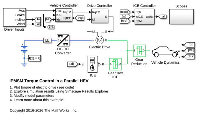
A simplified parallel hybrid electric vehicle (HEV). An interior permanent magnet synchronous machine (IPMSM) and an internal combustion engine (ICE) provide the vehicle propulsion. The IPMSM operates in both motoring and generating modes. The vehicle transmission and differential are implemented using a fixed-ratio gear-reduction model. The Vehicle Controller subsystem converts the driver inputs into torque commands. The vehicle control strategy is implemented as a Stateflow® state machine. The ICE Controller subsystem controls the torque of the combustion engine. The Drive Controller subsystem controls the torque of the IPMSM. The Scopes subsystem contains scopes that allow you to see the simulation results.
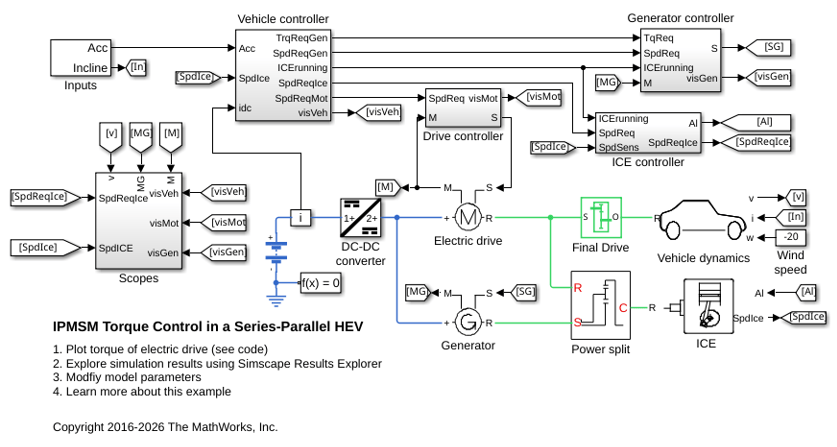
IPMSM Torque Control in a Series-Parallel HEV
A simplified series-parallel hybrid electric vehicle (HEV). An interior permanent magnet synchronous machine (IPMSM) and an internal combustion engine (ICE) provide the vehicle propulsion. The ICE also uses electric generator to recharge the high-voltage battery during driving. The vehicle transmission and differential are implemented using a fixed-ratio gear-reduction model. The Vehicle Controller subsystem converts the driver inputs into torque commands. The vehicle control strategy is implemented as a Stateflow® state machine. The ICE Controller subsystem controls the torque of the combustion engine. The Generator Controller subsystem controls the torque of the electric generator. The Drive Controller subsystem controls the torque of the IPMSM. The Scopes subsystem contains scopes that allow you to see the simulation results.
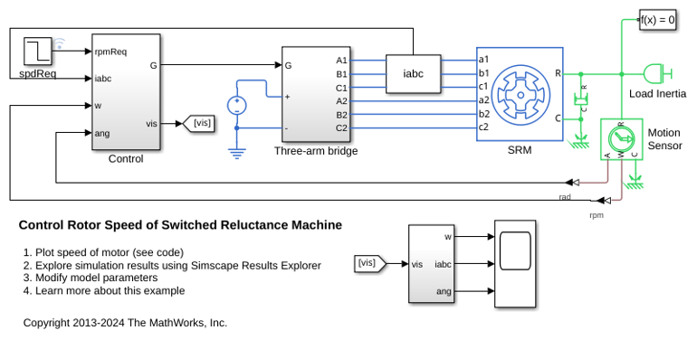
Switched Reluctance Machine Speed Control
Control the rotor speed in a switched reluctance machine (SRM) based electrical drive. A DC voltage source feeds the SRM through a controlled three-arm bridge. To achieve both forward and backward rotation, this example adjusts the converter turn-on and turn-off angles using the speed error.
Ports
Input
Output
Parameters
References
[1] IEEE Recommended Practice for Excitation System Models for Power System Stability Studies. IEEE Std 421.5/D39. Piscataway, NJ: IEEE-SA, 2015.

