Fault Annotations
In a custom component, you model fault behavior and triggering logic by using parameters,
variables, equations, conditional expressions, and other Simscape™ language constructs. The Faults annotation
provides the necessary information to the Simscape faults interface, which lets you model fault behaviors and trigger faults during
simulation.
Syntax Rules
To model faults for a component, define the relevant parameters, variables, equations, and conditional expressions and include a component-level annotation.
annotations
  Faults = Fault(Name                     = 'FaultName', ...
                 Switch                   = logical_p, ...
                 Values                   = [p1, p2], ...
                 ExternalTrigger          = in1, ...
                 TriggerType              = fault_trigger_type, ...
                 BehavioralTriggerValues  = [p3, p4], ...
                 Status                   = logical,
                 Transient                = true);
end
You can list the annotation elements in any order. Name,
Switch, Values, and
ExternalTrigger are required. For more information on the individual
elements, see Faults.
A component can have only one Faults annotation
section. You can define multiple faults as an array:
annotations
  Faults = [Fault(Name = 'Armature winding', Switch = ...)
            Fault(Name = 'Series field winding', Switch = ...)
            Fault(Name = 'Shunt field winding', Switch = ...)]
end
Custom Component with Fault Modeling
This example shows a custom linear resistor that models an electrical fault as an instantaneous change in resistance.
First, model this fault behavior without connecting it to the Simscape faults interface, just by using the Simscape language constructs.
component faultedResistorExtTrigger
% Linear Resistor with External Trigger Fault
% The voltage-current (V-I) relationship for a linear resistor is V=I*R,
% where R is the constant resistance in ohms.
%
% The resistor models an electrical fault as an instantaneous change in resistance.

  nodes
    p = foundation.electrical.electrical; % +:left
    n = foundation.electrical.electrical; % -:right
  end
  variables
    i = { 0, 'A' };     % Current
    v = { 0, 'V' };     % Voltage
  end

  branches
    i : p.i -> n.i;
  end

  equations
    v == p.v - n.v;
  end

  parameters
    R = {1, 'Ohm'}; % Resistance

    % Fault model parameters
    enableFault = false
    faultedResistance = {1000, 'Ohm'}
  end
  inputs
    externalFaultTrigger = 0
  end

  if ~enableFault
      equations
          v == i*R
      end
  else
      equations
          if ~externalFaultTrigger
              v == i*R
          else
              v == i*faultedResistance
          end
      end
  end

end
The fault is triggered by an external physical signal. Under nominal working conditions,
the voltage-current relationship is v = i*R. If you switch the logical
parameter enableFault to true, the blocks continues
under nominal conditions as long as the control signal at port
externalFaultTrigger is not zero. When the signal at that port
changes to zero, the block replaces the Resistance parameter value,
R, with the faultedResistance parameter value.
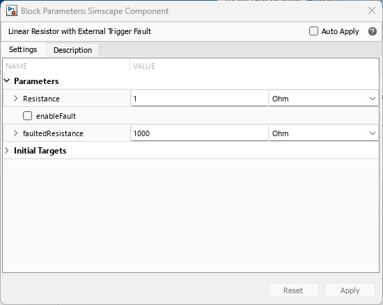
When you generate a custom block from this component, the block dialog box contains all the parameters. You must connect a physical signal to the input port externalFaultTrigger and provide the appropriate values to this signal, for example, to trigger the fault at a certain time.

Now, add the Faults annotation, to enable the block
to take advantage of the Simscape faults interface.
component faultedResistorExtTrigger
% Linear Resistor with External Trigger Fault
% The voltage-current (V-I) relationship for a linear resistor is V=I*R,
% where R is the constant resistance in ohms.
%
% The resistor models an electrical fault as an instantaneous change in resistance.

  nodes
    p = foundation.electrical.electrical; % +:left
    n = foundation.electrical.electrical; % -:right
  end
  variables
    i = { 0, 'A' };     % Current
    v = { 0, 'V' };     % Voltage
  end

  branches
    i : p.i -> n.i;
  end

  equations
    v == p.v - n.v;
  end

  parameters
    R = {1, 'Ohm'}; % Resistance

    % Fault model parameters
    enableFault = false
    faultedResistance = {1000, 'Ohm'}
  end
  inputs
    externalFaultTrigger = 0
  end

  if ~enableFault
      equations
          v == i*R
      end
  else
      equations
          if ~externalFaultTrigger
              v == i*R
          else
              v == i*faultedResistance
          end
      end
  end

  annotations
    Faults = Fault(Name                    = "Resistance", ...
                   Switch                  = enableFault, ...
                   Values                  = faultedResistance, ...
                   ExternalTrigger         = externalFaultTrigger)
  end
end
The annotation:
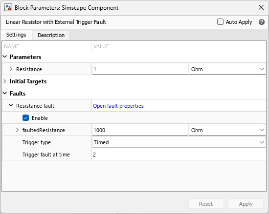
Gives the fault a name,
Resistance. This name identifies the fault in the Simscape faults interface: in the Fault Table, in the Faults section of the block dialog box, and so on.Associates the fault
Switchwith theenableFaultparameter. This parameter is now represented by the Enable check box in the Faults section of the block dialog box, under the fault name.Indicates that the
faultedResistanceparameter is related to faulted behavior. This parameter now appears in the Faults section of the block dialog box, under the fault name.Associates the fault
ExternalTriggerwith the inputexternalFaultTrigger. This input no longer appears on the block icon as an input physical port. Instead, it becomes part of the Simscape faults interface.

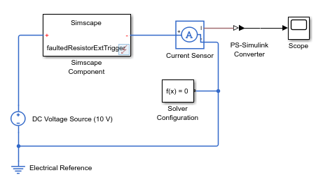
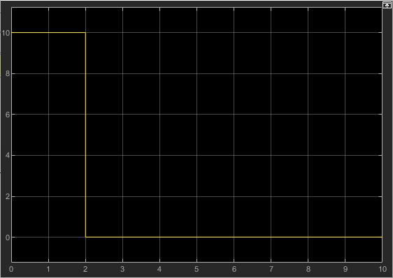
Now, when you put the custom block in a model, you can use the Simscape faults interface to enable and trigger faults during simulation. For more information, see Introduction to Simscape Faults.

