Specifying Component Connections
About the Structure Section
The structure section of a Simscape™ file is executed once during compilation. This section contains information on how the constituent components’ ports are connected to one another, as well as to the external inputs, outputs, and nodes of the top-level component.
The structure section begins with a connections keyword
and is terminated by an end keyword. This connections block
contains a set of connect constructs, which describe
both the conserving connections (between nodes)
and the physical signal connections (between the inputs and outputs).
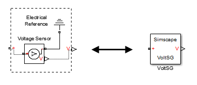
In the following example, the custom component file includes the Foundation library Voltage Sensor and Electrical Reference blocks and specifies the following connections:
Positive port of the voltage sensor to the external electrical conserving port + of the composite component
Negative port of the voltage sensor to ground
Physical signal output port of the voltage sensor to the external output of the composite component, located on the right side of the resulting block icon

component VoltSG
  nodes
     p = foundation.electrical.electrical; % +
  end
  outputs
     Out = { 0.0, 'V' }; % V:right
  end
  components(ExternalAccess=observe)
     VoltSensor = foundation.electrical.sensors.voltage;
     Grnd = foundation.electrical.elements.reference;
  end
  connections
     connect(p, VoltSensor.p);
     connect(Grnd.V, VoltSensor.n);
     connect(VoltSensor.V, Out);
  end
end
In this example, the first two connect constructs
specify conserving connections between electrical nodes. The third connect construct
is a physical signal connection. Although these constructs look similar,
their syntax rules are different.
Conserving Connections
For conserving connections, the connect construct
can have two or more arguments. For example, the connections in the
following example
  connections
     connect(R1.p, R2.n);
     connect(R1.p, R3.p);
  end
can be replaced with
  connections
     connect(R1.p, R2.n, R3.p);
  end
The order of arguments does not matter. The only requirement is that the nodes being connected are all of the same type (that is, are all associated with the same domain).
In the following example, the composite component consists of three identical resistors connected in parallel:
component ParResistors
  nodes
     p = foundation.electrical.electrical;
     n = foundation.electrical.electrical;
  end
  parameters
    p1 = {3 , 'Ohm'};
  end
  components(ExternalAccess=observe)
    r1 = foundation.electrical.elements.resistor(R=p1);
    r2 = foundation.electrical.elements.resistor(R=p1);
    r3 = foundation.electrical.elements.resistor(R=p1);
  end
  connections
    connect(r1.p, r2.p, r3.p, p);
    connect(r1.n, r2.n, r3.n, n);
  end
end
Connections to Implicit Reference Node
The * symbol indicates connections to a reference
node in branch statements. You can also use it
to indicate connections to an implicit reference node within the structure
section of a component:
connections
    connect(A, *);
end
The implicit reference node acts as a virtual grounding component. A node connected to an implicit reference has all its Across variables equal to 0.
The * symbol is not domain-specific, and
the same structure section can contain connections to implicit reference
in different domains:
component abc
    nodes
        M = foundation.mechanical.rotational.rotational;
        N = foundation.electrical.electrical;
    end
    connections
        connect(M,*);
        connect(N,*);
    end
end
However, multiple ports connected to an implicit reference within
the same connect statement must all belong to the
same domain:
connections
    connect(a, b, *);
end
The order of ports does not matter. This behavior is consistent with general connection rules for multiple conserving ports.
Physical Signal Connections
Physical signal connections are directional, therefore the connect construct
has the following format:
connect(s, d);
where s is the signal source port and d is
the destination port.
There can be more than one destination port connected to the same source port:
connect(s, d1, d2);
The source and destination ports belong to the inputs or outputs member
classes. The following table lists valid source and destination combinations.
| Source | Destination |
|---|---|
| External input port of composite component | Input port of member component |
| Output port of member component | Input port of member component |
| Output port of member component | External output port of composite component |
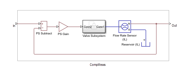
For example, consider the following block diagram.

It represents a composite component CompMeas,
which, in turn, contains a composite component Valve Subsystem,
as well as several Foundation library blocks. The Simscape file
of the composite component would specify the equivalent signal connections
with the following constructs.
| Construct | Explanation |
|---|---|
connect(In, subt.I1); | Connects port In to the input port + of the PS Subtract block. Illustrates connecting an input port of the composite component to an input port of a member component. |
connect(subt.O, gain.I); | Connects the output port of the PS Subtract block to the input port of the PS Gain block. Illustrates connecting an output port of a member component to an input port of another member component at the same level. |
connect(flow_rate_sensor.M, subt.I2, Out); | Connects the output port M of the Flow Rate Sensor
(IL) block to the input port - of the
PS Subtract block and to the output port
Out of the composite component. Illustrates connecting a
single source to multiple destinations, and also connecting an output port of a
member component to an output port of the enclosing composite component. |
Also notice that the output port of the PS Gain block is connected to the input port Conn2 of the Valve Subsystem composite block, which is another member component at the same level. Valve Subsystem is a standalone composite component, and therefore if you connect the output port of the PS Gain block to an input port of one of the member components inside the Valve Subsystem, that would violate the causality of the physical signal connections (a destination port cannot be connected to multiple sources).
Nonscalar Physical Signal Connections
Multidimensional physical signals can be useful for:
Aggregating measurements at different spatial points, such as temperatures along a coil or a 2-D grid of elements
Using 3-D body positions or velocities
Using rotation matrices or quaternions in 3-D
Using tensors
Simscape language supports nonscalar (vector-valued or
matrix-valued) physical signals in inputs and outputs declarations.
All signals in such vector or matrix should have the same units. For
example, the following declaration
 inputs
   I = {zeros(3), 'm/s'}; % :left
 end
initializes a component input as a 3-by-3 matrix of linear velocities.
When you connect input and output ports carrying nonscalar physical signals, you can use signal indexing and concatenation at the source, but not at the destination. Scalar expansion is not allowed.
The following table shows valid syntax examples, assuming subcomponent
A with output signal port A.o is being connected
to subcomponent B with input signal port B.i, and
all sizes and units are compatible.
| Construct | Explanation |
|---|---|
connect(A.o(1,2), B.i); | Source indexing, to connect to a scalar destination: take entry (1,2) of the output A.o and connect it to the input B.i. |
connect(A.o(1:2:5,2:3), B.i); | Index by rows and columns to specify a submatrix. |
connect(A.o(1:2:end,:), B.i); | Use colon notation to specify array boundaries (pass every other column of the output A.o to input B.i. |
connect([A1.o, A2.o], B.i); | Concatenate outputs A1.o and A2.o column-wise and pass the result to the input B.i. |
You can use block parameter values for indexing inside a connect statement,
for example:
connect(a.o(value( param_name,
'1'), 3), b.i);
When you connect two physical signals, their units must be directly
convertible. If one of the signals is declared as unitless (that is,
with units of '1') , then you can
connect a signal with any base units to it. However, unit conversion
is not supported in this case. For example, if a.i is
a 2x1 unitless input port, then this statement is valid:
connect([out1_in_meters, out2_in_seconds], a.i);
If you connect signals with different scales of the same unit with a unitless input port, the compiler alerts you to the fact that unit conversion is ignored. For example, the following statement produces a warning at compile time:
connect([out1_in_km, out2_in_mm], a.i);