Component Variants — Thermal Resistor
The following example shows a linear resistor with an optional thermal port. The component
uses conditional sections to implement the control logic. The
annotations sections within the conditional branches
selectively expose or hide appropriate ports, parameters, and variables based on the value of
the control parameter. The two block variants have a different number of ports, and therefore
the custom block icon also changes accordingly.
component CondResistor
% Linear Resistor with Optional Thermal Port
% If "Model thermal effects" is set to "Off", the block represents a
% linear resistor. The voltage-current (V-I) relationship is V=I*R,
% where R is the constant resistance in ohms.
%
% If "Model thermal effects" is set to "On", the block represents a
% resistor with a thermal port. The resistance at temperature T1 is given by
% R(T) = R0*(1+alpha(T1-T0)), where R0 is the Nominal resistance at the
% Reference temperature T0, and alpha is the Temperature coefficient.

nodes
    p = foundation.electrical.electrical; % +:left
    n = foundation.electrical.electrical; % -:right
    H = foundation.thermal.thermal;       % H:left
end

parameters
    thermal_effects = simscape.enum.onoff.off; % Model thermal effects
end

parameters(ExternalAccess=none)
    R = { 1, 'Ohm' };         % Nominal resistance
    T0 = {300,'K'};           % Reference temperature
    alpha = {50e-6,'1/K'};    % Temperature coefficient
    tc = {10,'s'};            % Thermal time constant
    K_d = {1e-3,'W/K'};       % Dissipation factor
end

variables(ExternalAccess=none)
    i = { 0, 'A' };                                         % Current
    v = { 0, 'V' };                                         % Voltage
    T1 = {value = {300,'K'}, priority = priority.high};  % Temperature
end

branches
    i : p.i -> n.i;
end

equations
    v == p.v - n.v;
end

if thermal_effects == simscape.enum.onoff.off
    annotations
        % Show non-thermal settings
        Icon = 'custom_resistor.png';
        [R, i, v] : ExternalAccess=modify;
        % Hide thermal node
        H : ExternalAccess=none;
    end
    connections
        connect(H, *); % Connect hidden thermal node to reference
    end
    equations
        R*i == v;
        T1 == T0;    % Temperature is constant
    end

else
    annotations
        % Show thermal settings
        Icon = 'custom_resistor_thermal.png';
        [T1, T0, alpha, tc, K_d, H] : ExternalAccess=modify;
    end

    % Add heat flow + thermal equations
    variables(Access=private)
        Q = { 0, 'J/s' }; % Heat flow
    end
    branches
        Q : H.Q -> *
    end
    equations
        T1 == H.T;
        let
            mc = tc*K_d; % mc in Q = m*c*dT
            % Calculate R(T), protecting against negative values
            Rdem = R*(1+alpha*(T1-T0));
            R_T = if Rdem > 0, Rdem else {0,'Ohm'} end;
        in
            R_T*i == v; % Electrical equation
            mc * der(T1) == Q + R_T*i*i; % Thermal equation
        end
    end

end
end
The component initially declares all the optional parameters and variables with the
ExternalAccess attribute set to none, and then exposes
them selectively by using the conditional annotations
sections. The opposite method, of hiding inapplicable members, is also valid, but this
approach is more easily scalable when you have multiple component configurations.
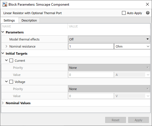
If the control parameter, Model thermal effects, is set to
Off, the block represents a linear resistor. The only exposed
block parameter is Nominal resistance, the Initial
Targets section lets you set targets for Current and
Voltage, and the block icon has two ports, + and
-.


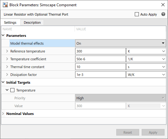
If the Model thermal effects parameter is set to
On, the block represents a resistor with a thermal port, with
temperature-dependent resistance. The block parameters, variable initialization targets,
ports, and the custom block icon change accordingly.

