AC Voltage Source
理想的恒定电压源

库:
Simscape /
Foundation Library /
Electrical /
Electrical Sources
描述
AC Voltage Source 模块表示理想的电压源,它能保持其输出端子上的正弦电压不变,与流过该电压源的电流无关。
输出电压由以下方程定义:
其中:
V 是电压。
V0 是峰值振幅。
f 是频率。
φ 是相移。
t 是时间。
连接端 + 和 - 是分别对应于电压源的正极端子和负极端子的守恒电气端口。如果电流从正极流向负极,则电流为正,电压源两端的电压等于正极端子电压与负极端子电压之差,即 V(+) – V(-)。
示例
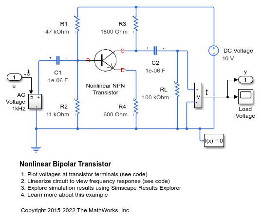
非线性双极晶体管
此模型展示了一个基于 Ebers-Moll 等效电路的非线性双极晶体管的实现。R1 和 R2 设定标称工作点,小信号增益由比值 R3/R4 近似设定。选择了 1uF 去耦电容器,它在 1KHz 时的阻抗可以忽略不计。该模型被配置为线性化,以便产生频率响应。
端口
守恒
参数
扩展功能
版本历史记录
在 R2007a 中推出