Main Content

Choked Flow in Gas Orifice

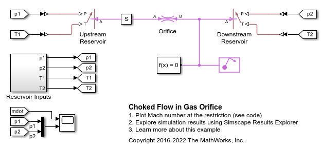
This example shows the choking behavior of a gas orifice modeled by the Local Restriction (G) block. The Controlled Reservoir (G) blocks are used to set up controlled pressure and temperature boundary conditions from the Reservoir Inputs subsystem to test the gas orifice.

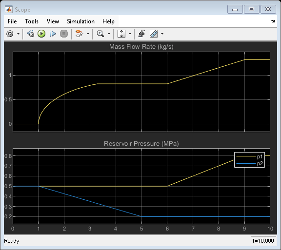
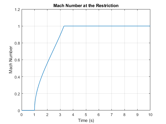
At the start, the flow is unchoked. Mass flow rate increases as the downstream pressure decreases. At 3.3 s, the flow becomes choked. The choked mass flow rate depends only on the upstream conditions, so further decrease in the downstream pressure does not cause a further increase in the choked mass flow rate. However, at 6 s, the upstream pressure increases, so the choked mass flow rate increases again.

Model

Simulation Results from Scopes

Simulation Results from Simscape Logging