Validating Quadcopter Requirements and System Architecture with Simulation
This example demonstrates how to design and validate a quadcopter system using the model-based systems engineering (MBSE) approach. It uses System Composer™ and Requirements Toolbox™ to author and link requirements, build the architecture model, and iteratively analyze and improve the system design based on simulation results.
This workflow illustrates how to:
Define and link requirements for the quadcopter system
Develop a system architecture to simulate quadcopter behavior
Refine requirements based on simulation analysis
Update the architecture to meet the evolving requirements
Validate quadcopter behavior through requirements-based testing using Simulink Test™
Open Project
Open the project to load all required files and models. The project includes the requirements set, architecture model, and test suite for the quadcopter system.
openProject("ValidateQuadRequirements");Define System Requirements
Use Requirements Toolbox to author and manage requirements in the Requirements Editor. Requirements can be created directly or imported from third-party management tools such as ReqIF, Microsoft® Word, or Microsoft Excel®. For detailed instructions, see Import Requirements from Third-Party Applications (Requirements Toolbox).
In this example, the system-level requirements that describe communication, UAV capability, and flight-control behavior are stored in SystemRequirements.slreqx. You can open the specification file in the Requirements Editor by double-clicking it in the project folder browser or using the Project Shortcuts. The Requirements Editor view below shows how this requirement is defined.
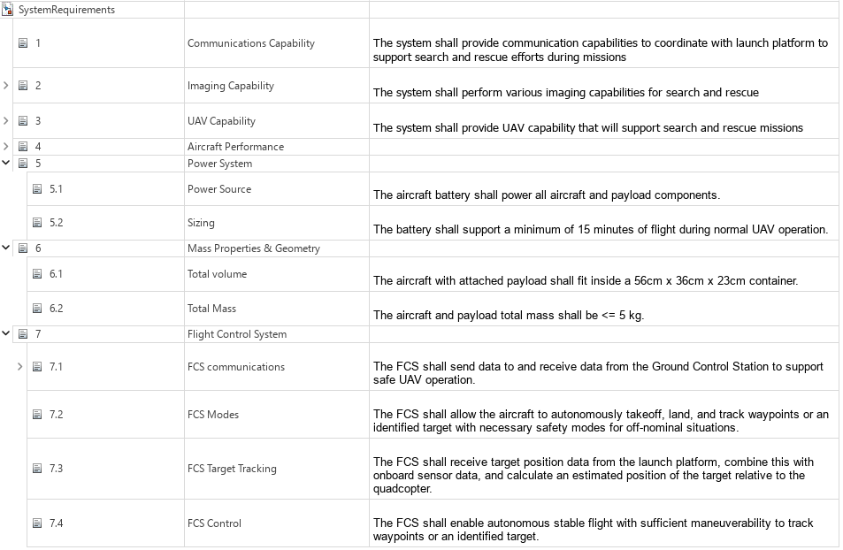
At the functional level, the system must support autonomous operations such as takeoff, waypoint tracking, and landing through a reliable closed-loop flight control system. The quadcopter must also maintain safe and reliable command and telemetry exchange with the Ground Control Station (GCS). These objectives form the basis for the initial architecture design. For more information about these system requirements, see Develop and Verify a Quadcopter System Architecture (System Composer).
Build System Architecture
Use System Composer to build an architecture model that represents two-way communication between the GCS and the quadcopter. The main components of the architecture model are:
GroundControlStation: Sends control commands to the quadcopter and receives telemetry data.
Threat: Simulates an attacker capable of intercepting and injecting spoofed commands into the communication channel.
AirVehicle: Represents the quadcopter, which executes incoming commands and transmits its state and telemetry.
Visualization: Displays the real-time state and behavior of the quadcopter for monitoring and analysis.
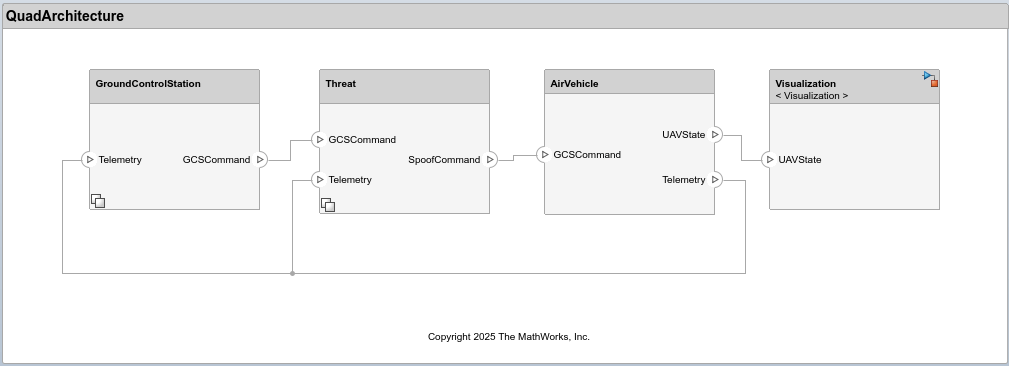
The architecture models the command and telemetry workflow between the GCS and the quadcopter. The GroundControlStation transmits GCSCommand messages to control the quadcopter and receives Telemetry data reporting its status and performance. The Threat component can intercept GCSCommand messages and inject malicious SpoofCommand messages while observing the Telemetry feedback.
The initial simulation focuses on autonomous flight capabilities and therefore assumes normal, interference-free communication. The NoThreat variant within the Threat component captures this baseline condition by passing GCSCommand messages directly to AirVehicle. The AirVehicle executes incoming commands—whether genuine or spoofed, transmits its current state as UAVState, and relays Telemetry information to both GroundControlStation and Threat components. The Visualization component receives UAVState data and animates the quadcopter behavior.
The GroundControlStation and Threat components use variant subsystems to represent different communication protocols and threat conditions. This enables simulation of multiple configurations within a single architecture model, supporting iterative refinement of requirements and subsequent evolution of the system architecture.
Simulate Normal Operation with MAVLink Protocol
The Micro Air Vehicle Link (MAVLink) is a widely used, open-source communication protocol for drones and unmanned vehicles. It defines a lightweight, message-based format that enables reliable exchange of commands and telemetry between the GCS and the quadcopter. MAVLink’s standardized message structure allows interoperability across different autopilot systems and GCS software, making it a common choice in UAV development and testing. For more information, see MAVLink Developer Guide | MAVLink Guide. The integration of this protocol within the quadcopter architecture is accomplished using MAVLink Support (UAV Toolbox).
To simulate normal quadcopter operation using the MAVLink protocol, use the default parameter values stored in the Simulink data dictionary (SLDD). In this example, QuadData.sldd manages and stores data for the architecture and models. For more information on editing architectural data, see Architectural Data Editor.
The parameters varComms, varThreat, and landTime define the communication protocol, threat condition, and landing time (in seconds), respectively. In the default configuration, varComms is set to 1 to enable MAVLink communication, varThreat is 0 to represent normal operation without any threat, and the landing time (landTime) of the quadcopter is 12 seconds.
When varThreat = 0, the NoThreat model executes and directly passes GCSCommand as SpoofCommand, indicating that no threat intervention occurs.
Run the simulation:
mdl = "QuadArchitecture";
out = sim(mdl);
### Searching for referenced models in model 'QuadArchitecture'. ### Total of 1 models to build. ### Starting serial model build. ### Successfully updated the model reference simulation target for: AirVehicle Build Summary Model reference simulation targets: Model Build Reason Status Build Duration ======================================================================================================= AirVehicle Target (AirVehicle_msf.mexa64) did not exist. Code generated and compiled. 0h 0m 22.008s 1 of 1 models built (0 models already up to date) Build duration: 0h 0m 26.757s
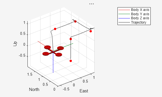
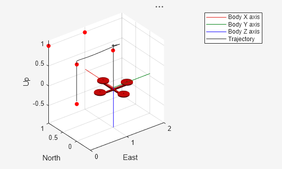
The UAV animation demonstrates that the quadcopter follows the predefined reference waypoints, shown as red markers, and initiates landing at the specified landTime. Note that the reference waypoints are defined as waypoints in the SLDD. For more information on the guidance and control implementation, see Develop and Verify a Quadcopter System Architecture (System Composer).
Simulate Threat with MAVLink Protocol
Although MAVLink is efficient and widely adopted, its open and lightweight design introduces security vulnerabilities. Because the message format is publicly documented and the protocol lacks built-in authentication or encryption, an adversary with access to the communication channel can potentially read, modify, or inject commands that appear legitimate. Such spoofed control messages can lead to unauthorized actions or unsafe behavior in the quadcopter.
Assume an attacker within radio range can observe MAVLink traffic and inject forged messages. For threat modeling, this example further assumes that
Threat hardware (for example, commodity radios) can physically intercept the communication channel.
Transport-layer specifics (such as Ethernet or Bluetooth) do not influence the vulnerability.
Detect Spoofing Vulnerabilities
The first step in a spoofing threat is for an attacker to observe the telemetry stream to learn which messages are exchanged and what fields they contain. MAVLink requires the quadcopter to periodically send a HEARTBEAT message, which exposes identifier and mode fields that an attacker can use to craft believable spoofed messages. The structure of the MAVLink HEARTBEAT message is shown below:
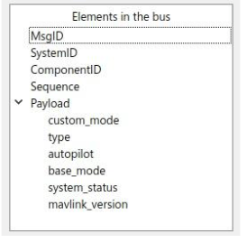
If an attacker can receive the HEARTBEAT messages, they can obtain the necessary system and component IDs and the current mode information needed to communicate with the quadcopter and select payload values that appear legitimate. A key field in the HEARTBEAT message is base_mode, which encodes the quadcopter’s flight mode. By monitoring base_mode over time, an attacker can infer which mode values correspond to specific behaviors and then attempt to inject or replay spoofed commands using those values.
Plot the base_mode from the simulation logs:
plot(out.logsout.getElement('<base_mode>').Values,'LineWidth',2);
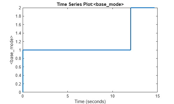
From the plotted data, the base_mode values map to,
base_mode = 0— initialization modebase_mode = 1— autonomous flight mode (tracking)base_mode = 2— automatic landing mode
The mode transitions from initialization through autonomous flight and to landing are clearly visible in the plot. An attacker observing the same trace could experiment with other base_mode values not present in the trace to explore their impact on the quadcopter behavior.
Simulating the Threat
The ThreatMAV model simulates the spoofing attack by injecting the SET_MODE message with base_mode = 3 at the specified spoof time. Open the ThreatMAV model under the Threat component in the architecture to understand its implementation. The spoofed command sets the base_mode in the AirVehicle subsystem to 3.
To simulate this scenario, set varComms to 1 to use the MAVLink protocol, varThreat to 1 to activate the ThreatMAV model, and spoofTime to 7 seconds to define when the spoof occurs. The following code updates these values in the SLDD and runs the simulation.
% Open the associated SLDD
qdd = Simulink.data.dictionary.open(get_param('QuadArchitecture','DataDictionary'));
dd = qdd.getSection('Design Data');

% Configure parameters for the spoofing scenario
evalin(dd,'varComms = 1;varThreat = 1;spoofTime = 7;');

% Run the simulation
out = sim(mdl);
### Searching for referenced models in model 'QuadArchitecture'.
### Total of 1 models to build.
### Model reference simulation target for AirVehicle is up to date.

Build Summary

0 of 1 models built (1 models already up to date)
Build duration: 0h 0m 0.63575s
Plot the quadcopter altitude to verify the impact of the threat at the specified spoof time.
plot(out.logsout.getElement('Altitude').Values)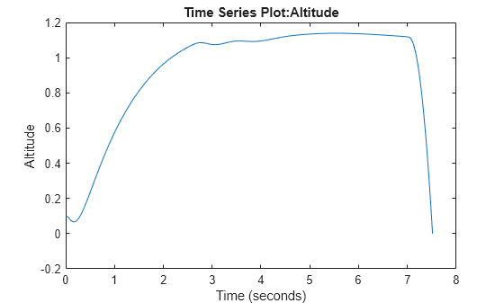
A sudden drop in altitude around the spoof time indicates that the injected SET_MODE command altered the quadcopter behavior, triggering an unintended transition to the EmergencyOff mode.
Risk Assessment with MAVLink Protocol
Evaluate the risk of a spoofing attack on the quadcopter by considering both the probability of occurrence and its potential impact.
Probability of Occurrence (Medium): A spoofing attempt is possible if an adversary is within radio range and understands the MAVLink protocol.
Extent of Damage (High): A successful spoof could disrupt flight control and cause a crash, leading to hardware loss and safety hazards.
Generate the design risk matrix that maps the identified threat according to its likelihood and impact.
createDesignRiskMatrix(mdl);
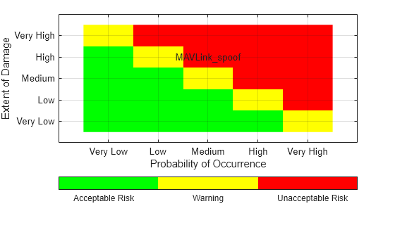
The resulting plot shows that the spoofing threat with MAVLink protocol falls in the high-impact, medium-probability zone, indicating an unacceptable risk that requires mitigation in the system architecture.
Introduce Security Requirement
The threat simulation demonstrates that MAVLink’s openly documented message format leaves the communication channel vulnerable to spoofing. This drives the introduction of the following security requirement: "The communication channel between the Ground Control Station (GCS) and the UAV shall use a custom protocol that is not publicly documented." This requirement is stored in SecurityRequirement.slreqx, as shown below:
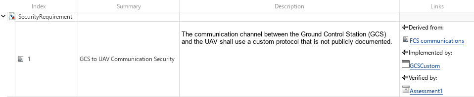
Using a custom, non-public protocol makes the message format significantly harder for an attacker to decode, interpret, or replicate, thereby improving system resilience. This refinement illustrates a key aspect of the MBSE workflow: requirements evolve in response to simulation analysis, and the architecture is systematically updated to incorporate the resulting system-level decisions.
Develop Countermeasure with Custom Communication Protocol
In this example, the custom protocol replaces MAVLink with a compact, byte-oriented message format. Each command is represented by a specific bit within a single byte, creating a minimal and non-standard encoding scheme. For instance, bit 0 corresponds to Takeoff, bit 1 to Land, and bit 2 to EmergencyOff. This encoding makes the command intent harder to infer, since the message structure and meaning of each bit are not easily discernible. An attacker would need to deduce that setting bit 2 (value 4; 00000100) triggers EmergencyOff. This increases ambiguity and improves spoof resistance, as a successful spoofing attempt would require significantly greater effort to decode the bit assignments and associated logic.
The Byte Unpack (Embedded Coder) block decodes the incoming message into individual fields, such as the custom header, communication counter, and command message. Bitwise operations are then carried out to construct the command message. The Byte Pack (Embedded Coder) block subsequently assembles these fields into a compact byte array and outputs it as GCSCommand. Open the GCSCustom model under the GroundControlStation component to view the implementation of the custom communication protocol.
Simulate the Custom Protocol
To simulate the custom protocol, set varComms to 2 to enable the custom communication protocol, while keeping spoofTime = 7 seconds and varThreat = 1 to execute the threat model. The following code updates varComms in the SLDD and runs the simulation.
evalin(dd,'varComms = 2;');
out = sim(mdl);
### Searching for referenced models in model 'QuadArchitecture'. ### Total of 1 models to build. ### Model reference simulation target for AirVehicle is up to date. Build Summary 0 of 1 models built (1 models already up to date) Build duration: 0h 0m 0.44373s

The UAV animation shows that the spoofed command no longer causes unintended behavior in the quadcopter, demonstrating that the countermeasure based on the custom communication protocol effectively mitigates the spoofing threat.
Risk Assessment with Custom Protocol
Evaluate the risk of a spoofing attack on the quadcopter using the custom communication protocol.
Probability of Occurrence (Low): The custom protocol reduces the likelihood of a successful spoofing attempt, as its message structure is not easily predictable.
Extent of Damage (High): Despite the lower probability, a successful spoofing attack could still disrupt flight control, leading to hardware loss and safety hazards.
Recreate the design risk matrix to reflect the use of the custom communication protocol.
createDesignRiskMatrix(mdl);

The resulting plot shows that this countermeasure effectively shifts the risk to the low-probability, high-impact region of the matrix. Though the extent of damage remains the same, the lower probability reflects improved system resilience and validates the effectiveness of the implemented custom communication protocol.
Validate System Requirement
While UAV Animation helps visualize and analyze quadcopter behavior, Simulink Test automates the requirements-based testing process by building and executing test cases. This provides a scalable and systematic framework for verifying that the system meets its defined requirements.
This example contains a test file, QuadcopterTests.mldatx. Open it from the project folder or using the project shortcut to view it in the Test Manager.
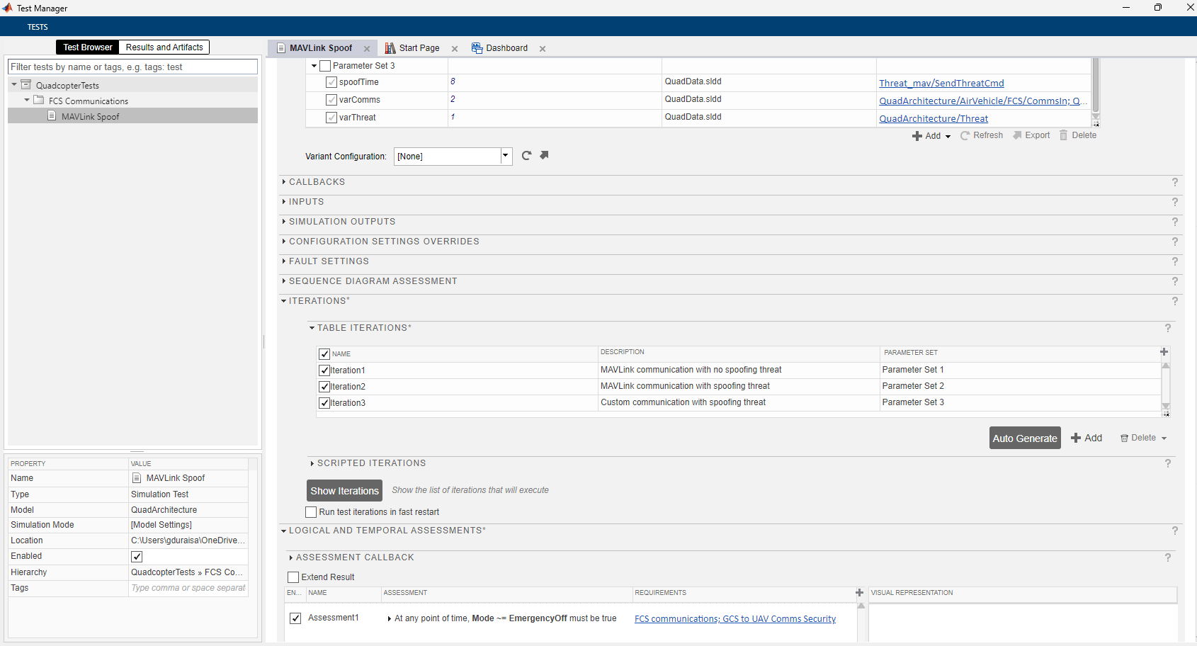
The test file defines three iterations under the Iterations section:
Iteration 1 – MAVLink communication with no threat
Iteration 2 – MAVLink communication with threat
Iteration 3 – Custom communication with threat
Parameter values for each iteration are set in the Parameter Overrides section of the Test Manager. All three iterations are evaluated using a common assessment to verify that the Mode signal of the quadcopter never equals EmergencyOff at any point during the simulation. This assessment is defined in the Logical and Temporal Assessments section and is linked to the security requirement.
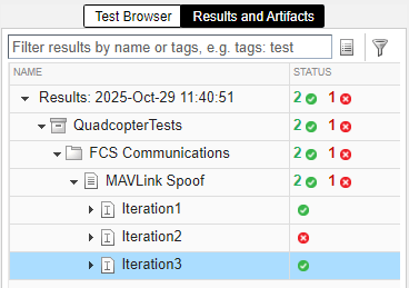
Run the test iterations in the Test Manager. As expected, the first iteration passes since no threat is introduced and the quadcopter operates normally. The second iteration fails because the MAVLink protocol is spoofed by the threat, triggering an emergency landing. By contrast, the custom protocol cannot be spoofed, and the quadcopter continues to operate safely as validated in the third iteration.
For critical missions, you may consider encryption-based communication to further strengthen security, though it introduces computational and implementation overhead. In this example, adopting a lightweight custom protocol provides a practical balance between security robustness and cost, demonstrating how MBSE helps evaluate design trade-offs early in development.
Discard changes to SLDD
Use discardChanges function to revert any unsaved changes to the data dictionary. This ensures that the shipping SLDD remains clean and validated for each run. To retain your edits, comment out or remove this line before running the script.
discardChanges(Simulink.dictionary.archdata.open("QuadData.sldd"));See Also
Topics
- Requirements Editor (Requirements Toolbox)
- Develop and Verify a Quadcopter System Architecture
- Project Management