Synthesize Engine Noise Using Android Devices
This example shows how to use the Simulink® Support Package for Android® Devices to synthesize a realistic engine noise using the Wavetable Synthesizer (Audio Toolbox) block.
Prerequisites
For more information on how to use the Simulink Support Package for Android Devices to run a Simulink model on your Android device, see Getting Started with Android Devices.
For more information on how to get started with audio signal processing on Android devices, complete the Get Started with Audio Signal Processing Using Android Devices and Synthesize Variable Frequency Tones Using Android Devices examples.
Required Hardware
Android device such as a phone or tablet
USB cable
Headphones with microphones
Hardware Setup
Connect your Android device to the host computer using the USB cable.
Connect the headphones to your Android device.
Configure Simulink Model and Calibrate Parameters
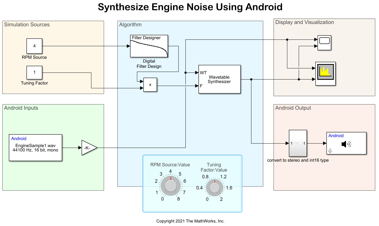
Open the androidAudioSynthesizer Simulink model.

Simulation Sources
The RPM Source and Tuning factor Constant blocks represents the RPM source of the machine engine and the gain of the machine noise, respectively. Use these Constant blocks to set the RPM and gain of the noise signal in the simulation environment. Set the RPM Constant block to 4 and the Tuning Factor Constant block to 1.
Android Inputs
The EngineSample1.wav file in the Audio File Read block is a wavetable sample recorded at an unspecified RPM.
Algorithm
The Wavetable Synthesizer block receives these two inputs:
Single-cycle waveform — Recorded output of the wavetable sample from the Audio File Read block,
EngineSample1.wavfile.Output-wave frequency — Tuning factor multiplied by RPM source output from lowpass filter.
Tune the RPM to adjust the perceived RPM of the generated engine sound. The RPM source is lowpass smoothed using a Digital Filter Design block. The tuning factor can be used to increase or decrease the overall range of output frequencies.
Configure these parameters in the Block Parameters dialog box of the Digital Filter Design (DSP System Toolbox) block.
1. In the Design Method section, set IIR to Butterworth.
2. In the Filter Order section, set Specify order to 2.
3. In the Frequency Specifications section, set these parameters.
a. Units to Hz.
b. Fs to 44100/2048.
c. Fc to 1.
Configure these parameters in the Block Parameters dialog box of the Wavetable Synthesizer block.
Select Specify wavetable from input port.
Select Specify frequency from input port.
Set Samples per frame to
2048.Set Output data type to
single.
Display and Visualization
In the Display and Visualization area, you can view the filtered signals in the Time Scope and Spectrum Analyzer blocks.
Android Outputs
The audio signal output from the Wavetable Synthesizer block is converted from single to int16 data type in the convert to stereo and int16 type subsystem and then played on the Android speaker using the Audio Playback block.
Run Simulink Model
On the Simulation tab of the model, click Run. Listen to the engine sound output from the Wavetable Synthesizer.
Change the RPM and tuning factor values and observe the time scope and spectrum analyzer outputs to adjust the perceived RPM of the generated engine sound.

Deploy Simulink Model on Android Device
1. On the Hardware tab of the Simulink model, in the Mode section, click Run on board. In the Deploy section, click Build, Deploy & Start. The androidAudioSynthesizer application launches automatically on your Android device.
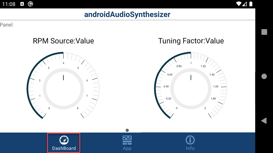
2. On the Dashboard tab of the application, use the knobs to change RPM and tuning factor of the noise signal.

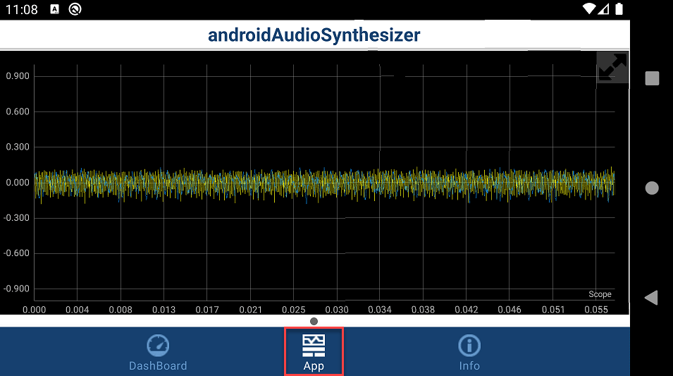
3. On the App tab of the application, observe the corresponding change in the noise signal.

4. Connect your headphones to the Android device and listen to the tone change as you tune the RPM and tuning factor values of the noise signal.