Line Follower Application for Arduino Robot
This example shows how to create a line follower algorithm in Simulink® and how to run it on an Arduino® Robot.
Introduction
Simulink Support Package for Arduino Hardware enables you to create and run Simulink models on Arduino Robot. This Robot has two Leonardo (ATmega32u4) based boards: Arduino Robot Motor Board and Arduino Robot Control Board. The Arduino Robot Control Board has peripherals such as Analog Input Pins, Digital Input/ Output Pins, PWM, Keypad, Potentiometer (POT), Compass, Buzzer, etc. The Arduino Robot Motor Board has peripherals such as Analog Input Pins, Digital Input/ Output Pins, PWM, Motor Driver, Motors, Wheels, Trimming Potentiometer (TRIM), IR sensors, etc. For more details, refer to the Arduino Robot website.
This example shows how to create a Simulink model to run a line follower algorithm on the Arduino Robot Motor board by accessing the IR sensors and motors. You will learn how to access the peripherals of the Arduino Robot Motor Board using blocks from the Simulink library and the standard Arduino library from the Simulink Support Package for Arduino Hardware.
This example illustrates how to access the peripherals (Keypad, Buzzer) of the Arduino Robot Control Board using blocks from Simulink library and the standard Arduino library. You will learn how to establish serial communication between the Arduino Robot Control Board and the Arduino Robot Motor Board.
Prerequisites
If you are new to Simulink, we recommend completing the Interactive Simulink Tutorial, Get Started with Simulink, and Simulink Getting Started video.
Required Hardware
To run this example you will need the following hardware:
Arduino Robot
USB Cable
Four rechargeable NiMh AA batteries
9V Adapter
Track drawing on A0 white sheet with ~ 1.5" wide black line
Introduction to Line Follower Application
A line follower mechanism for the Arduino Robot can be shown as below:

In this application you need to get the current deviation of the Arduino Robot from the center of the black line to get the Error signal. Based on the Error signal you will drive the motors on the Arduino Robot Motor Board to take corrective action and bring the Arduino Robot back to the center of the black line.
1. On examining the Arduino Robot you will notice that the IR sensors present on the Arduino Robot Motor Board can be used to obtain the current deviation of the Arduino Robot from the center of the black line. You will learn to read the values from the IR sensors using blocks from the Simulink library and the standard Arduino library.
2. You will learn how to provide pulse width modulated (PWM) signals to control the motors connected to the Arduino Robot Motor Board and spin the wheels to move the Arduino Robot.
Task 1 - Create Simulink Subsystem to Read IR Sensors on Arduino Robot Motor Board
In this section, you will learn how to decode IR Sensor values into a Simulink signal of dimensions 5 corresponding to the number of IR sensors present on the Arduino Robot Motor Board. The logic described is implemented in the IR sensors subsystem. For more information on the Arduino Robot Motor Board, refer to the Arduino Robot website. Notice the following connections for the IR sensors:
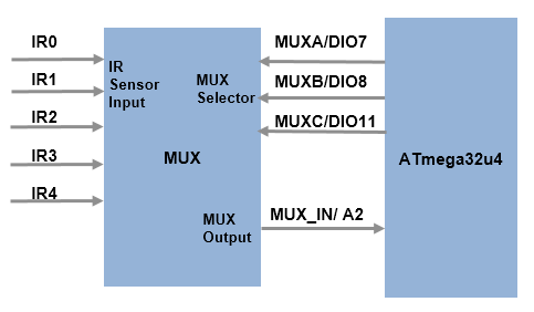
Five IR sensors (IR0-IR4) are connected to the input channels of a multiplexer (MUX). The MUX selectors MUXA, MUXB, MUXC are connected to digital pins 7, 8, and 11 respectively on the microcontroller. The microcontroller can only read one IR sensor at a time, by providing 3 digital signals (MUXA, MUXB, MUXC) to select the desired IR sensor signal on the output of the MUX. 3 digital signals are enough to access the 5 IR sensors. MUXA is the LSB and MUXC is the MSB of the selector byte. Based on the selector byte, the following IR sensor is selected:
MUXC | MUXB | MUXA | IR sensor_number
_ _ _ _ _ _ _ _ _ _ _ _ _ _ _ _ _ _ _
 0   |  0   |  0   |  0
 0   |  0   |  1   |  1
 0   |  1   |  0   |  2
 0   |  1   |  1   |  3
 1   |  0   |  0   |  4
_ _ _ _ _ _ _ _ _ _ _ _ _ _ _ _ _ _ _
The selected IR sensor, present on the MUX output, is connected to the analog pin A2 of the microcontroller.
The following steps will show you how to create a masked subsystem in Simulink to read an IR sensor.
1. Use a Constant block to decide which IR sensor to read. Take a Constant block from Library: Simulink > Sources and update the following settings: Constant Value -> any value from 0-4, Sample Time -> 0.002, Output data type -> uint8. The values 0-4 correspond to the IR sensor numbers.
2. Convert the IR sensor number into a binary value to provide inputs to the digital pins corresponding to MUXA, MUXB, MUXC using Bitwise Operator block. Use 3 Bitwise Operator blocks with AND operation and values 0x1, 0x2, 0x4 which gives LSB to MSB respectively for the selector byte. Use 3 Digital Output blocks from Library: Simulink Support Package for Arduino Hardware > Common and populate the Pin number as 7, 8, 11 for MUXA, MUXB, MUXC respectively. Connect the LSB of the selector byte (obtained from the AND operation) to Digital Output block corresponding to MUXA, middle bit to MUXB, MSB to MUXC.
3. Use an Analog Input block from Library: Simulink Support Package for Arduino Hardware > Common to read pin A2 corresponding to the MUX output. Enter Pin number 2 and a sample time of 0.001. The Analog Input block reads a value of data type uint16 ranging from 0-1023 from the IR sensor (where 0 - white and 1023 - black). Use a Data Type Conversion block to convert the value to int16. Connect the output of Data Type Conversion block to an Outport.
4. Set the priority of the Digital Output blocks to 1 as the selector byte needs to be written before reading IR sensor value. Set the priority of the Analog Input block to any value > 1 to ensure it gets executed after the selector byte is written to MUX. To set the Priority of a block, right-click the block > Properties > General > Priority. To know more about block priorities and their impact on block execution order, refer to Specify Block Properties.
5. Use a For Iterator Subsystem to loop through all the 5 sensors. The input to the For Iterator Subsystem is the Constant block created in Step 1. The value of the Constant block is [0 1 2 3 4] to represent all the 5 sensors. Use Outport for the output of the For Iterator Subsystem.
6. Place the blocks created from step 2-4 inside the For Iterator Subsystem. Open the For Iterator subsystem inside the IR sensors subsystem and check the settings of Selector and Assignment blocks. The Selector and Assignment blocks are used to loop through one IR sensor number at a time and assign the value to the output vector.
7. Create a subsystem by selecting all the blocks created in step 6 such that it looks as below:

Task 2 - Create Simulink Subsystem to Control Motors on Arduino Robot Motor Board
In this section, you will learn how to spin two motors present on the Arduino Robot Motor Board in both forward and reverse directions using desired Torque Simulink signals. The logic described is implemented in the Motors subsystem. The schematic of the Arduino Robot Motor Board shows the following connections between the microcontroller and the motor driver:
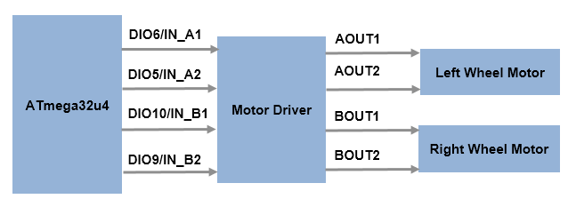
The motor driver controls the speed and the direction of both left and right motors by taking inputs from the microcontroller. Notice that the digital pins 6, 5, 10, 9 of the microcontroller are connected to IN_A1, IN_A2, IN_B1, IN_B2 of the motor driver. The inputs IN_A1, IN_B1 of the motor driver corresponds to the forward movement of the left and right motor respectively. IN_A2, IN_B2 corresponds to the reverse movement of the left and right motor respectively.
A pulse width modulated (PWM) signal can be used to control the motors. A positive input to the motor driver from the microcontroller corresponds to forward movement of the motors, whereas a negative input corresponds to reverse movement of the motors. For forward movement of both the motors, you apply the PWM signals to IN_A1 and IN_B1 and zero values to IN_A2 and IN_B2. Similarly for reverse movement, you apply the PWM signals only to IN_A2 and IN_B2 and zero values to IN_A1 and IN_B1.
The following steps show you how to create a masked subsystem in Simulink to control the motors.
1. Use an Inport blocks to get the input from the microcontroller for the left motor.
2. The PWM block present in Library: Simulink Support Package for Arduino Hardware > Common can be used to send PWM signals to control the motors. Use 2 PWM blocks and enter the pin numbers 6, 5 for IN_A1, IN_A2.
3. The relation between the input value and IN1 (IN_A1/ IN_B1), IN2 (IN_A2/ IN_B2) can be shown as below:
Input | IN1       | IN2
_ _ _ _ _ _ _ _ _ _ _ _ _ _ _ _
+ve   | Input     | 0
-ve   | 0         | abs(Input)
_ _ _ _ _ _ _ _ _ _ _ _ _ _ _ _
For the forward movement, use a MUX block to multiplex input value and a Constant block of 0 value of data type int16.
4. The PWM block accepts values from 0-255 (uint8). For the reverse movement, use an Abs block with Output data type -> int16, Integer rounding mode -> Round to convert the negative input value to positive and multiplex it with the Constant block used in step 3 with value 0.
5. Use a Switch block with condition u2 > Threshold where u2 -> input and Threshold -> 0. If the condition is met then the forward movement multiplexed values are selected else reverse movement multiplexed values are selected.
6. Use a DEMUX block and connect the outputs to the 2 PWM blocks corresponding to IN_A1, IN_A2.
7. Repeat the entire logic from steps 1-6 for the right motor. Enter pin number 10, 9 for the 2 PWM blocks corresponding to IN_B1, IN_B2.
8. Create a subsystem by selecting all the blocks.
Task 3 - Build Simulink Model with Line Follower Algorithm
In this section, the line follower algorithm is implemented as a closed-loop control system with PID controller. The logic described is implemented in the Line Follower Algorithm subsystem. The algorithm is described below:

The blue dots represent IR sensors (IR0 - IR4). When the Arduino Robot is at the center of the black line then IR2 reads black (~1023) and IR0, IR1, IR3, IR4 read white (~0). A threshold is chosen to convert the range from 0-1023 to a binary value. 1 when below the threshold (bright or white background), 0 when above the threshold (dark or black background).
A weight is given to each sensor, with higher values to the extreme ones providing higher control signals when higher deviation is detected. The weighted current deviation is calculated from the below equation:

When the robot is centered on a thin black line, IR2 reads 0 while IR0, IR1, IR3, IR4 read 1.
Substituting the values in the equation, the current deviation is calculated as below:

The Desired deviation when the robot is centered on a thin black line is set to a constant value of 0. The error is calculated as  . In this case when the current deviation is 0, the error is 0 and the robot can move straight. A summarized list of all possible errors is shown in the below table:
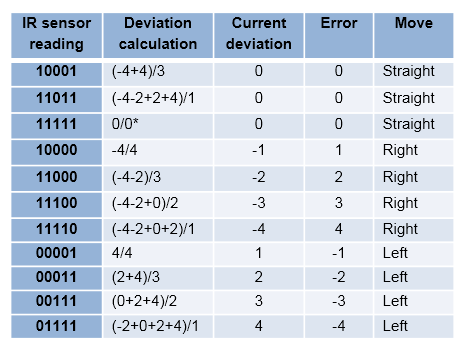
* - divide-by-zero case
Notice that a positive error means right turn for the Arduino Robot > Left Motor torque increases, Right Motor torque decreases. A negative error for the Arduino Robot means left turn > Left Motor torque decreases, Right Motor torque increases.
To implement the above mentioned line follower logic in Simulink you can create two subsystems: one to get the current deviation of the Arduino Robot using IR sensors and another to control the motors. An example of the implementation can be seen in the Line Follower Algorithm subsystem of the model.
1. Look inside the Current deviation calculation subsystem. It gives the current deviation of the Robot from the center of black line as per the above algorithm.
Points to note:
The IR sensor threshold value set to a constant value of 600.
The weights applied using Gain blocks
Saturate on integer overflow option checked for Math Function block
Integer rounding mode as Round for Product block to ensure the current deviation represents accurate integer value.
Switch block to take care of the possible divide-by-zero case for current deviation calculation.
2. Analyze the Torque estimation subsystem. It gives the desired torque values (from -255 to 255) for the left and the right motors.
Points to note:
The Base Torque of the Robot set to a constant value of 100. The Output data type set to int16 to match the data type of Torque_correction.
Stateflow® chart implementation switches between three different states: GoStraight, TurnLeft, TurnRight based on value of Torque_direction.
3. Observe that the IR sensors subsystem has a priority of 1 and that the Motors subsystem has much lower priority say, 5 to ensure the control action is applied to the motors only after obtaining the current deviation of the Robot from the IR sensors.
4. In this example a Discrete PID controller block is used to get the control action based on the error. You may need to tune the P, I, D values iteratively by placing the Robot on the track. Make sure that the batteries are charged enough to run the wheels properly.
Task 4 - Run Line Follower Application on Arduino Robot Motor Board
In this section, you will learn the steps required to deploy the Simulink Algorithm on the Arduino Robot Motor Board.
1. Connect the Arduino Robot Motor Board to your host computer using USB cable. This cable would also power the board.
2. In the model, click Simulation > Model Configuration Parameters to open Configuration Parameters dialog box. In the dialog box that opens, select the Hardware Implementation pane Select and Arduino Robot Motor Board as Hardware board from the dropdown menu. You can either manually select the COM Port number or let it remain Automatically and keep the rest of the settings with default values. Then click Apply > OK.
Open the arduinorobot_linefollower Simulink model.
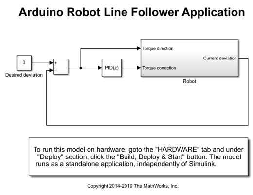
3. On the Hardware tab of the Simulink model, in the Mode section, select Run on board and then click Build, Deploy & Start.
4. After the model is downloaded, disconnect the USB cable from your Arduino Robot Motor Board.
5. Place the Robot on the track and turn the Robot power switch on present at the Arduino Robot Motor Board. The model runs on the Arduino Robot Motor Board and the Arduino Robot starts moving.
6. Factors such as ambient light and thickness of the track can affect the ability of the Robot to track the black line. If the Arduino Robot does not track the black line. To overcome these issues, you can tune the P, I, D values of the Discrete PID Controller and change the values of Base Torque, IR sensor threshold in the model to make the Robot track the black line. Download the model again on the Arduino Robot Motor Board using Build, Deploy & Start option. Repeat till the Arduino Robot follows the black line properly.
7. Turn the Robot switch off.
Task 5 - Extend Simulink Model with Serial Communication Between Arduino Robot Control Board and Arduino Robot Motor Board
In this section, you will learn how to establish serial communication between the Arduino Robot Motor Board and the Arduino Robot Control Board. You will learn how to decode the Keypad signals on the Arduino Robot Control Board and how to use them as control signals on the Arduino Robot Motor Board. The logic described is implemented in arduinorobot_controlboard and arduinorobot_motorboard Simulink models.
This example uses the Keypad and Buzzer peripherals present on the Arduino Robot Control Board to send control commands to and react on the feedback received from the Arduino Robot Motor Board. For more information on the Arduino Robot Motor Board, refer to the Arduino Robot website. The schematic shows that the Keypad is connected to pin A0 of the Arduino Robot Control Board. The Keypad has 5 keys controlling a voltage divider circuit. The voltage detected after a key press is represented by a 10-bit (0-1023) analog to digital value on the microcontroller. Depending on the digital representation of voltage at pin A0 you can know which key is pressed.
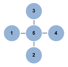
A0_Digital_Value | Key
_ _ _ _ _ _ _ _ _ _ _ _ _
0-10             | 1
133-153          | 2
319-339          | 3
494-514          | 4
732-752          | 5
_ _ _ _ _ _ _ _ _ _ _ _ _
The schematic of the Arduino Robot Control Board shows that the Buzzer is connected to digital pin D5.
You can control the movement of wheels on the Arduino Robot Motor Board by pressing a key on the Arduino Robot Control Board and play a tone on Buzzer based on feedback received from the Arduino Robot Motor Board. Serial communication is used for data transmission between the two boards.
a) Sending serial commands from Keypad of Arduino Robot Control Board:
You can read the key pressed on the Arduino Robot Control Board. Key 5 can be used to switch between two modes of the Robot: Line Follower mode and Manual mode. Based on the selected mode and the key pressed you can send serial commands to Arduino Robot Motor Board. The below table summarizes the data sent serially by Arduino Robot Control Board:
Mode          | Key pressed |       Move              | Serial data
_ _ _ _ _ _ _ _ _ _ _ _ _ _ _ _ _ _ _ _ _ _ _ _ _ _ _ _ _ _ _ _ _ _
Line Follower | NA          | track black line center |  1
Manual        | none        | stop                    |  0
Manual        | 1           | counterclockwise        |  2
Manual        | 2           | backward                |  3
Manual        | 3           | forward                 |  4
Manual        | 4           | clockwise               |  5
_ _ _ _ _ _ _ _ _ _ _ _ _ _ _ _ _ _ _ _ _ _ _ _ _ _ _ _ _ _ _ _ _ _
NA - Not Applicable
1. Open the arduinorobot_controlboard Simulink model.
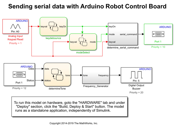
To know the key pressed you can use Analog Input block from Library: Simulink Support Package for Arduino Hardware > Common with Pin number 0 and Sample time 0.004.
2. Observe the key debounce logic using Stateflow chart that validates the key press if the key remains pressed for 0.016 s. Note that the key debounce time may vary from one Robot hardware to another.
3. The modeSelect Stateflow chart detects if the key 5 is pressed and switches from Line Follower mode to Manual mode and vice-versa. Note that the default mode is Line Follower. Any key press other than 5 does not have any effect on the Line Follower mode.
4. The serial command subsystem determines the data to be sent in the Line Follower or the Manual mode. In the Manual mode, you can make the Robot move as per the data sent by the key press to the Arduino Robot Motor Board.
5. Use Serial Transmit block from Library: Simulink Support Package for Arduino Hardware > Common with Port 1 to send the commands to the Arduino Robot Motor Board. The Serial Transmit block has initial value of 1 indicating the Line Follower mode as default.
6. Note that the priority of Analog Input Keypad Read block is 1 and that of Serial Transmit block is much lower say, 10. This ensures that you determine the pressed key before sending the commands serially.
b) Receiving serial data on Arduino Robot Motor Board and sending feedback:
1. Open the arduinorobot_motorboard Simulink model.
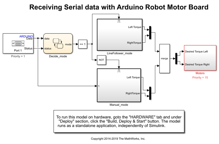
To receive the serial data from Arduino Robot Control Board a Serial Receive block from Library: Simulink Support Package for Arduino Hardware > Common is used with Port 1 and Sample time 0.002. Note that the Serial Receive block has a higher sampling rate than the Serial Transmit block on the arduinorobot_controlboard Simulink model to ensure not to miss any data.
2. Observe the decide mode Stateflow chart used to decide the mode to be followed by the Arduino Robot Motor Board. The default mode is Line Follower. Note that the Status output of the Serial Receive block indicates if any new data is received. The Stateflow chart uses the Status information to switch between the modes accordingly.
3. See the enabled subsystem Line Follower mode has the line follower algorithm placed inside it.
4. The Manual mode enabled subsystem uses a Switch Case block. The data received from the Arduino Robot Control Board selects the corresponding move from the Case subsystems. The default move is Stop i.e. both Left Motor Input and Right Motor Input is 0.
5. Depending on the selected move by the Switch Case block a Serial Transmit block (with Port 1) sends feedback to the Arduino Robot Control Board. Value of 1, 2, and 0 is sent as feedback. Value 1 corresponds to counterclockwise or clockwise move selection. Value 2 corresponds to forward or backward move selection. Value 0 corresponds to default move of Stop.
6. The priority of the Switch Case block is higher (1) than the priority of the Serial Transmit block (20).
7. You can see that both the Line Follower mode and the Manual mode subsystems give the torque for the left and the right motor as outputs. These outputs are merged using Merge block and given as inputs to Motors subsystem. The priority of Serial Receive block is higher than the Motors subsystem.
c) Receiving the feedback serially on Arduino Robot Control Board:
1. Open the arduinorobot_controlboard Simulink model. The Serial Receive block with Port 1 and Sample time 0.002 receives the feedback from the Arduino Robot Motor Board.
2. The determine tone Stateflow chart uses the data received by Serial Receive block to determine the tone to play. A summary of received data and selected tone is given below:
Data received | Tone (Hz)
_ _ _ _ _ _ _ _ _ _ _ _ _
  1           | 50
  2           | 125
  0           | 0
_ _ _ _ _ _ _ _ _ _ _ _ _
3. Pulse Generator blocks are used to generate 50 Hz and 125 Hz frequency. A Constant block is used for 0 Hz.
4. These tones are merged using Merge block and given as input to Digital Output block from Library: Simulink Support Package for Arduino Hardware > Common. The Pin number is set to 5 corresponding to Buzzer.
5. The priority of the Serial Receive block is less than Serial Transmit and that of Buzzer block is least.
Task 6 - Run Simulink Models on Arduino Robot Control Board and Arduino Robot Motor Board
In this section, you will learn the steps required to deploy the Simulink Algorithm on the Arduino Robot Control Board and Arduino Robot Motor Board.
1. First connect the Arduino Robot Control Board to your host computer using USB cable.
2. In the arduinorobot_controlboard Simulink model, choose the Hardware board as Arduino Robot Control Board under Simulation > Model Configuration Parameters > Hardware Implementation. Select the COM Port either Manually or Automatically while keeping rest of the settings as default. On the Hardware tab of the Simulink model, in the Mode section, select Run on board and then click Build, Deploy & Start.
3. After the model is downloaded, disconnect the USB cable from your Arduino Robot Control Board.
4. Connect the Arduino Robot Motor Board to your host computer using USB cable.
5. In the arduinorobot_motorboard Simulink model, choose the Hardware board as Arduino Robot Motor Board under Simulation > Model Configuration Parameters > Hardware Implementation. Select the COM Port either Manually or Automatically while keeping rest of the settings as default. On the Hardware tab of the Simulink model, in the Mode section, select Run on board and then click Build, Deploy & Start.
6. After the model is downloaded, disconnect the USB cable from your Arduino Robot Control Board.
7. Place the Robot on the ground and turn the power switch on present on the Arduino Robot Motor Board. The model runs on the board and the Arduino Robot starts on the default mode of Line Follower. When you press Key 5 it switches from Line Follower to Manual mode and is stopped as per the default action under Manual mode. Then based on key press 1, 2, 3, or 4 it either moves counterclockwise, backward, forward, or clockwise as long as the key is pressed. Once you release the key the Robot is in Stop mode. On pressing Key 5, the Robot switches to Line Follower mode.
8. Turn the Robot switch off.
Other Things to Try
Verify the working of each subsystem for peripheral access by using some sample inputs. For example, you can use sample inputs through Constant blocks (values ranging from -255 to 255) to the subsystem to control motors to see if the wheels spin forward or backward.
Adjust the PID Controller settings. Improve the Robot's ability to move faster and take sharper turns.
The present example uses a constant IR sensor threshold value. Try to implement dynamic calculation of IR sensor threshold which can vary due to ambient light.
A constant value of Base Torque is used in this example. Try to adjust the Base Torque dynamically. For instance, you can make the Robot go faster by increasing the Base Torque for straight movement. To ensure smoother turns, you can decrease the Base Torque.
Try to access other peripherals present on the Arduino Robot Control Board and the Arduino Robot Motor Board. For example, explore sending of serial commands to Arduino Robot Motor Board from the Potentiometer on the Arduino Robot Control Board.