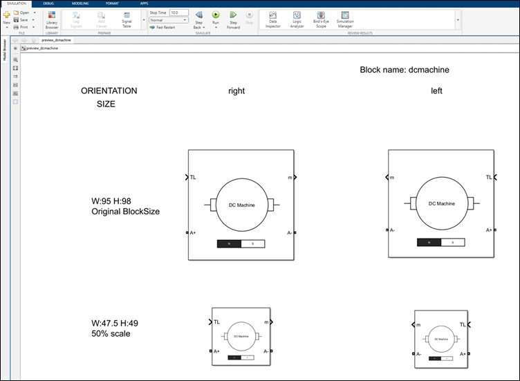
Create and Edit Block Mask Icon Using Graphical Icon Editor
Create block mask icon using Graphical Icon Editor. This example shows how to draw a block icon with the following features using the Graphical Icon Editor.
The icon has the elements as shown in the following image.
Depending on the value of the block parameter
FieldType, the permanent magnet or the spring is visible on the icon.The text that appears in the center of the icon takes the value of the block parameter
CenterTextdefined in the Mask Editor.
![]()
To create the block icon:
Add a Subsystem block. To create mask on the block, right-click the block and select Create Mask.
In the Icon tab, select Graphical.
Draw the icon.
Select Rect from the drawing tools and draw a square. A new part is created in the Element Browser. Click
 to pin this part to make it the base part of the
block mask icon. The elements in the base part appear in all other parts, reducing
the need to replicate icon elements.
to pin this part to make it the base part of the
block mask icon. The elements in the base part appear in all other parts, reducing
the need to replicate icon elements.Note
Enable the Grid and Snap to grid options in the toolstrip to precisely align shapes with each other.
Select Line from the drawing tools to draw a horizontal line touching the middle of the square.
Select the square and line elements and make a copy of them. Select the elements, right-click and select Group to group the square and the line. Select Flip Horizontal from the toolstrip to flip the copies horizontally.
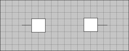
Select Ellipse to draw a circle joining the two squares.
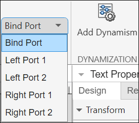
In the toolstrip, click Ports and then specify Left as
2and Right as2for specifying the number of ports.Use the Text tool to add the text element
DC
                  Machine
in the center of the icon.Click
 to create an another part for the bar magnet. Select
Rect and draw a rectangle. Make a copy of the rectangle and
place the rectangles next to each other. Use the Text tool to
add the text element
to create an another part for the bar magnet. Select
Rect and draw a rectangle. Make a copy of the rectangle and
place the rectangles next to each other. Use the Text tool to
add the text element NandS. Fill the left rectangle with black color.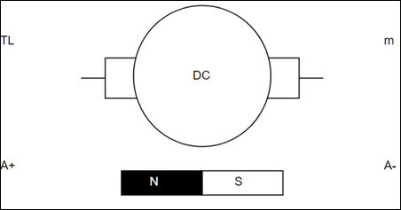
Click
to create an another part for the spring element. Select
Shape Finder, search for Inductor and
place it on the canvas. Flip the inductor element vertically. Adjust the edit points
of the inductor element to form the loops of the spring.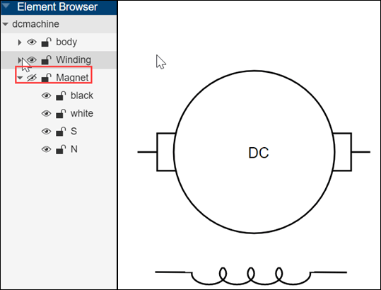
Note
You can rename the elements in the Element Browser for easy identification.
Bind ports to the icon by selecting Port Label and place it on the canvas.
Hide or unhide spring and magnet elements based on the block parameter condition.
Configure the spring element to be visible when the
FieldTypeparameter isWoundand the magnet element to be visible when theFieldTypeparameter isPermanent magnet. Create a Popup parameter in the Mask Editor namedFieldType. Specify the options asPermanent magnetandWound.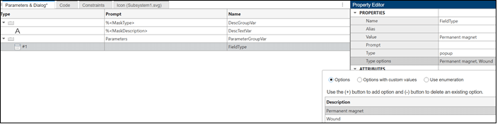
Select part with magnet and select Visibility Condition pane on the right side.
From the Condition Type list, select
Block
                  Parameters
. Select the parameter asFieldType, the condition asEqual toand the value asPermanent magnet. Click Apply to populate the visibility condition.
Set the magnet element to be visible when
FieldTypeisWoundin a similar way.
Create a text label that appears in the center of the icon..
Define the block mask parameter
CenterTextin the Mask Editor.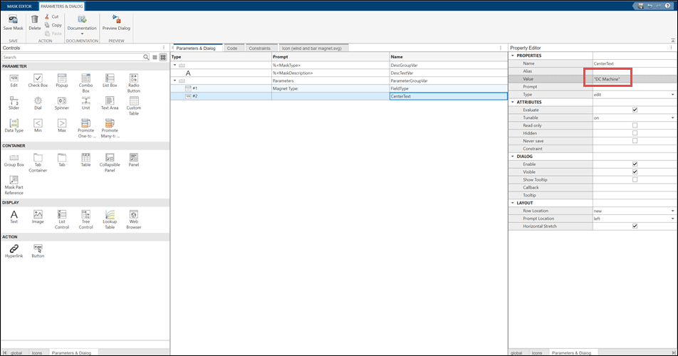
Select the part that holds the text element and then select the text element. In the Parameter Association pane, select the Text tab.
Enter the mask block parameter name
CenterTextin Parameter or Expression.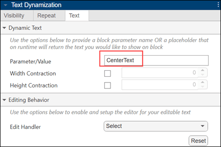
Parameter or Expression returns its value during run time.
Click Preview in Model from the toolstrip to preview the icon on the Simulink® canvas.
Click Save Mask to save the mask. Mask Editor also allows you to save the icon file with the model by checking Save with Model.