Main Content

Using Initialize, Reinitialize, Reset, and Terminate Functions

Some blocks maintain state information that they use during a simulation. For example, the Unit Delay block uses the current state of the block to calculate the output signal value for the next simulation time step.

Subsystem blocks have default initialize and termination routines. You can add custom routines to the default routines using Initialize Function, Reinitialize Function, and Terminate Function blocks to change or read block states. You can also implement custom routines using Reset Function blocks. These function blocks contain:

  • An Event Listener block that executes the combined routine when receiving an initialize, reinitialize, or terminate function-call event, or the custom routine when receiving a reset function-call event.

  • A State Writer block to initialize or set a block state or a State Reader block to read the state.

To define the custom routine, edit the contents of the block. For example:

  • Set the State owner block parameter of the State Writer or State Reader block.

  • Add additional State Writer or State Reader blocks.

  • Add Parameter Writer blocks to set the value of block parameters. See Initialize and Reset Parameter Values.

  • Add Data Store Write blocks to write or Data Store Read blocks to read data in a data store. See Model Global Data by Creating Data Stores.

  • Add blocks and signal lines to supply the values for State Writer, Parameter Writer, and Data Store Write blocks to write, or to save the values read by State Reader or Data Store Read blocks.

Create Model Component with State

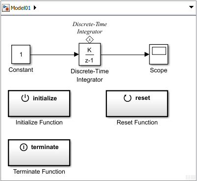
You can define model algorithms using Simulink® blocks. In this example, a single Discrete-Time Integrator block defines the algorithm for integrating an input signal.

  1. Open a new Simulink model. Save this model with the name Model01.

  2. Add a Discrete-Time Integrator block. Verify the default parameter values are 1.0 for Gain value, 0 for Initial condition, Auto for Initial condition setting, and -1 for Sample time.

  3. Connect a Constant block to the input of the Discrete-Time Integrator block to model an input signal. Connect a Scope block to the output signal.

  4. Open the Configuration Parameters dialog box. Set the simulation parameters for the Solver Type to Fixed-step, Solver to auto, and Fixed-step size to 1.

  5. Open the Scope block, and then run simulation. The output signal increases by 1 at each time step.

Initialize Block State

Some model algorithms contain states that you can initialize. For example, with an algorithm that reads a sensor value, you can perform a computation to set the initial sensor state.

At the beginning of a simulation, initialize the state of a block using a State Writer block. To control when initialization occurs, use an Initialize Function block that includes the State Writer block.

  1. Add an Initialize Function block.

    By default, the Initialize Function block includes an Event Listener block with the Event type parameter set to Initialize. The block also includes a State Writer block, and a Constant block as a placeholder for the source of the initial state value.

  2. Model initial conditions. In this example, set the Constant value parameter for the Constant block to 4.

  3. Connect the state writer with the state owner. Open the State Writer dialog box. Expand the State Owner Selector Tree, select Discrete-Time Integrator, and then click Apply.

    The State Writer block displays the name of the state owner block. The state owner block displays a tag indicating a link to a State Writer block. If you click the label above the tag, a list opens with a link for navigating to the State Writer block.

  4. Run a simulation to confirm that your model simulates without errors.

    The Initialize Function block executes at the beginning of a simulation. The output signal starts with and initial value of 4 and then increases by 1 until the end of the simulation.

Reset Block State

During a simulation, you can reset the state of a block using a State Writer block. To control when reset occurs, use a Reset Function block.

Note

You can use either a Reinitialize Function block or a Reset Function block to reset the state of a block. Both the Reinitialize Function block and the Reset Function blocks can write to block states or perform whatever actions you specify when you configure the blocks. The difference between the blocks is that a Reinitialize Function first implicitly resets the states of all blocks in the model back to their initial conditions and then carries out whatever other actions, including writing to block states, you specify when you configure the block. By contrast, a Reset Function block, carries out only the actions that you specify when you configure the block. In this example, since the model contains no other blocks with state besides the Discrete-Time Integrator block, a Reinitialize Function block could be used in place of the Reset Function block with no difference in results.

  1. Add a Reset Function block.

  2. Open the Reset Function block.

  3. Model reset conditions. In this example, set the Constant value parameter for the Constant block to 2.

  4. Connect state writer with the state owner. Open the State Writer block dialog box. Expand the State Owner Selector Tree, select Discrete-Time Integrator, and then click Apply.

  5. The event name for the Reset Function block, reset, is displayed on the face of the block.

    If you click above the tag, a list opens with a link for navigating to the State Writer blocks located in the Initialize Function block and the Reset Function block.

    Note

    If the Reset Function block were replaced by a Reinitialize Function block, then the Reinitialize Function block would first set the state of the Discrete-Time Integrator block back to its initial condition of 0, as specified in the Discrete-Time Integrator block dialog. The Reinitialize Function block would then use the State Writer block to set the state of the Discrete-Time Integrator block to 2, which would override the implicit reinitialization to 0. This sequence of actions has the same effect as the Reset Function block, which simply sets the state of the Discrete-Time Integrator block to 2.

    If a Reinitialize Function block were used without a State Writer block, then it would set the state of the Discrete-Time Integrator block to its initial condition of 0. If a Reset Function block were used without a State Writer block, it would have no effect on the state of any other block.

  6. Run a simulation to confirm that your model simulates without errors.

    The Reset Function block does not execute during the simulation. The block needs a function-call event signal.

    To create a function-call event signal for the Reset Function block, see Create Test Harness to Generate Function Calls.

Read and Save Block State

At the end of a simulation, you can read the state of a block, and save that state.

  1. Add a Terminate Function block.

    By default, the Terminate Function block includes an Event Listener block with the parameter Event type set to Terminate. The block also includes a State Reader block, and a Terminator block as a placeholder for saving the state value.

  2. Connect the state reader with the state owner. Open the State Reader block dialog box. From the State Owner Selector Tree, select Discrete-Time Integrator, and then click Apply.

  3. Run a simulation to confirm that your model simulates without errors. The Terminate Function block executes at the end of a simulation.

  4. Delete the blocks that you added for testing. Replace the Constant block with an Inport block and the Scope block with an Outport block.

Prepare Model Component for Testing

Make the following changes to avoid simulation errors when the component model is placed in an export-function model for simulation testing.

  1. Open the Block Parameters dialog box for the Discrete-Time Integrator block. Set Integrator method to Accumulation:Forward Euler.

  2. Open the Model Configuration Parameters dialog box. Confirm the solver Type is set to Fixed-step and Solver is set to auto. Change the Fixed-step size from 1 to auto.

    This change avoids a simulation error caused by having multiple sample times in a Function-Call Subsystem.

Create an Export-Function Model

Placing a model component in a test harness for testing the initialize, reset, and terminate functions requires the model to follow export-function rules. See Export-Function Models Overview and Create Test Harness to Generate Function Calls.

To create an export-function model, place the model component in a Function-Call Subsystem block using a Model block. Connect input and output ports from the model to the subsystem input and output ports.

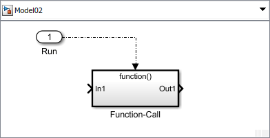
  1. Create a Simulink model. Save this model with the name Model02.

  2. Open the Configuration Parameters dialog box. Set the simulation parameter for the Solver Type to Fixed-step. Confirm Solver is set to auto and Fixed-step size is set to auto.

  3. Add a Function-Call Subsystem block. Open the subsystem by double-clicking the block.

  4. Add a Model block to the subsystem and set Model name to Model01. Add Inport and Outport blocks.

  5. Navigate to the top level of the model.

  6. Add an Inport block. This block is the control signal for executing the subsystem. Change the block name to Run and connect it to the function() port.

    Open the Inport block dialog box and on the Signal Attributes tab, select the Output function call check box.

  7. Add a second Inport block and rename it to Signal In. Connect it to the In1 port of the subsystem. This block is the signal for the integration algorithm.

    Add an Outport block, rename it to Signal Out, and then connect it to the Out1 port of the subsystem. This block is the integrated signal.

  8. Designate the model as an export-function model by going to the Property Inspector and setting the execution domain of the model to Export function. See Designating an Export-Function Model.

  9. Open the Configuration Parameters dialog box. On the Model Referencing pane, set the Total number of instances allowed per top model to one.

  10. Update your model and confirm that there are no errors by pressing Ctrl+D.

The next step is create a test harness. See Create Test Harness to Generate Function Calls.

See Also

| | | | | |

Related Topics

External Websites