Zero-Crossing Algorithms
The Simulink® software includes two zero-crossing detection algorithms: Nonadaptive and Adaptive.
To choose the algorithm, either use the Algorithm option in the
Solver pane of the Configuration Parameters dialog box, or use the
ZeroCrossAlgorithm parameter. The parameter value can either be set
to 'Nonadaptive' or 'Adaptive'.
The Nonadaptive algorithm is provided for backward compatibility with older versions of Simulink and is the default. It brackets the zero-crossing event and uses increasingly smaller time steps to pinpoint when the zero crossing has occurred. Although adequate for many types of simulations, the Nonadaptive algorithm can result in very long simulation times when a high degree of 'chattering' (high frequency oscillation around the zero-crossing point) is present.
The Adaptive algorithm dynamically turns the bracketing on and off, and is a good choice when:
The system contains a large amount of chattering.
You want to specify a guard band (tolerance) around which the zero crossing is detected.
The Adaptive algorithm turns off zero-crossing bracketing (stops iterating) if either of the following are satisfied:
The zero crossing error is exceeded. This is determined by the value specified in the Signal threshold option in the Solver pane of the Configuration Parameters dialog box. This can also be set with the
ZCThresholdparameter. The default isAuto, but you can enter any real number greater than zero for the tolerance.The system has exceeded the number of consecutive zero crossings specified in the Number of consecutive zero crossings option in the Solver pane of the Configuration Parameters dialog box. Alternatively, this can be set with the
MaxConsecutiveZCsparameter.
Signal Threshold for Adaptive Zero-Crossing Detection
The Adaptive algorithm automatically sets a tolerance for zero-crossing detection.
Alternatively, you can set the tolerance by entering a real number greater than or equal
to zero in the Configuration Parameters Solver pane, Signal threshold
pull down. This option only becomes active when the zero-crossing algorithm is set to
Adaptive.
This graphic shows how the Signal threshold sets a window region around the zero-crossing point. Signals falling within this window are considered as being at zero.
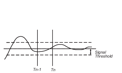
The zero-crossing event is bracketed by time steps Tn-1 and
Tn. The solver iteratively reduces the time steps until the
state variable lies within the band defined by the signal threshold, or until the number
of consecutive zero crossings equals or exceeds the value in the Configuration
Parameters Solver pane, Number of consecutive zero crossings pull
down.
It is evident from the figure that increasing the signal threshold increases the distance between the time steps which will be executed. This often results in faster simulation times, but might reduce accuracy.