Analyze Models Containing Simulink Functions Using Model Slicer
This example shows you how to analyze models that contain Simulink® functions using Model Slicer. You can visualize the interdependency of a Simulink function and Function Caller by adding them as starting points in Model Slicer. For more information on Simulink functions, see Simulink Functions Overview.
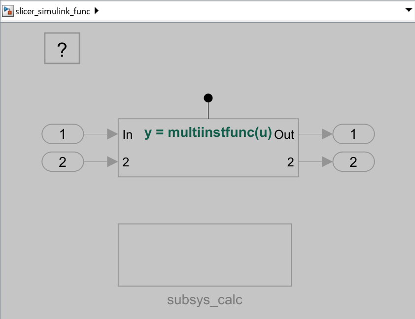
In this example, you visualize interdependencies between a Simulink Function and a Function Caller block in the upstream and downstream directions. The Simulink model slicer_simulink_func.slx contains the Simulink Function Caller subsys_calc.func_calc(), and its corresponding Simulink Function is defined in the subsys_calc subsystem.
Open the Model
1. Open the model slicer_simulink_func.
open_system('slicer_simulink_func')2. On the Apps tab, under Model Verification, Validation, and Test gallery, click Model Slicer.

Upstream Highlighting
1. In the Model Slicer window, set Signal propagation to upstream.
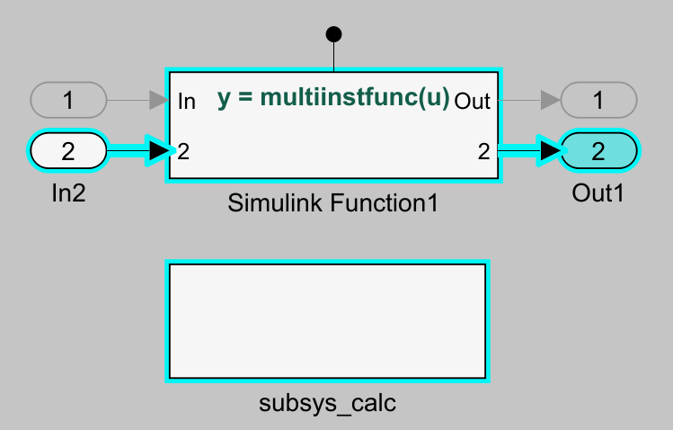
2. In the slicer_simulink_func model, select output Out1. Right-click Out1 and under Model Slicer, select Add as Starting Point. Model Slicer highlights the dependency of output Out1 in the upstream direction.

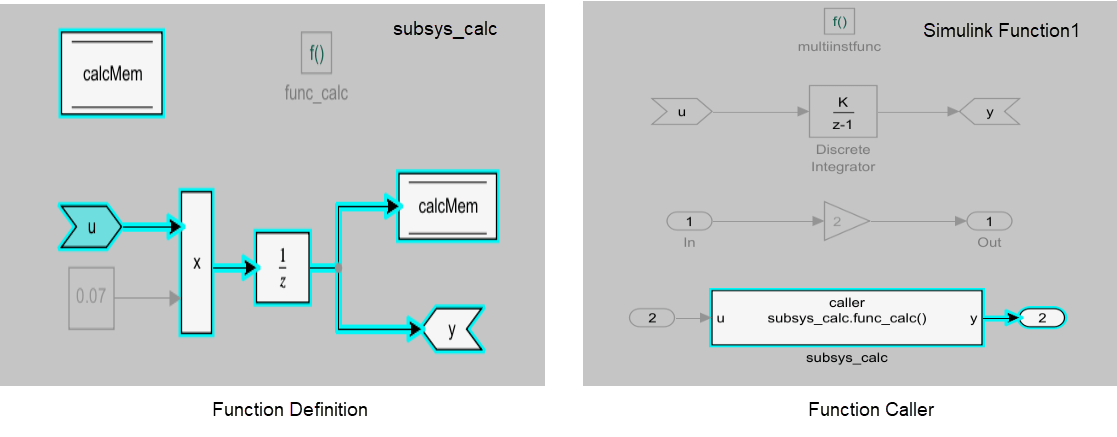
3. Double-click the Simulink Function1 and subsys_calc subsystem and you can observe the dependencies. Output Ou1 traces back to the Function Caller block subsys_calc.func_calc, the corresponding Simulink function for the block is defined in subsys_calc.

Downstream Highlighting
1. In the Model Slicer window, click clear all for Starting points and set the Signal propagation to downstream.
2. In the subsys_calc subsystem, select the ArgIn input parameter u as the starting point. Right-click u, and under Model Slicer, select Add as Starting Point. Model Slicer highlights the dependency of input u in the downstream direction from Function Caller subsys_calc.func_calc to the Simulink Function defined under susbys_calc.
