Refine Dependency Paths in Highlighted Model
After you highlight a model using Model Slicer, you can refine the dependency paths in the highlighted portion of the model. Using Model Slicer, you can refine a highlighted model by including only those blocks used in a portion of a simulation time window, or by excluding blocks or certain inputs of switch blocks. By refining the highlighted portion of your model, you can include only the relevant parts of your model.
Define a Simulation Time Window
You can refine a highlighted model to include only those blocks used in a portion of a simulation time window. Defining the simulation time window holds some switch blocks constant, and as a result removes inactive inputs.
1. Open the sldvSliceClimateControlExample model.
open_system("sldvSliceClimateControlExample");2. On the Apps tab, under Model Verification, Validation, and Test gallery, click Model Slicer.
When you open the Model Slicer, Model Slicer compiles the model. You then configure the model slice properties.
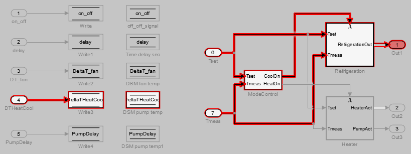
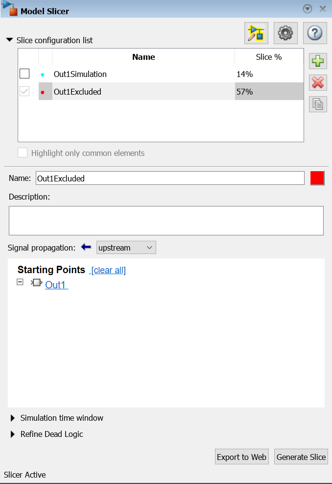
3. In the Model Slicer, click the arrow to expand the Slice configuration list.
4. Set the slice properties:
(a) Name: Out1Simulation
(b) Color: ![]() (cyan)
(cyan)
(c) Signal Propagation: upstream
5. In the top level of the model, select the Out1 block as the slice starting point. In the model, right-click Out1, and in the Model Slicer app section ![]() , select Add as Starting Point button
, select Add as Starting Point button ![]() .
.
The model is highlighted.
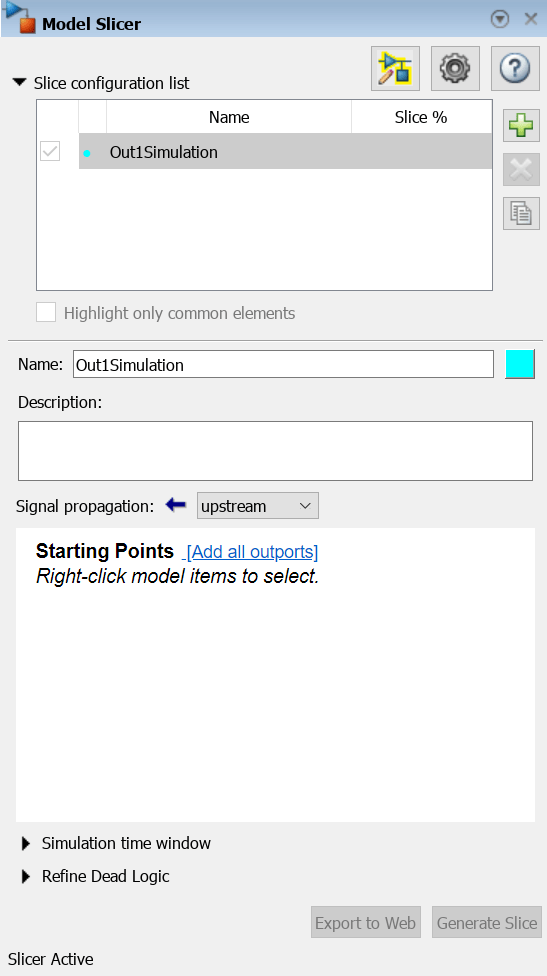
6. In the Model Slicer, select Simulation time window.
7. To specify the stop time of the simulation time window, click the run simulation button ![]() in the Model Slicer.
in the Model Slicer.
8. Set the Stop time to 10.
9. Click OK to start the simulation.

The path is restricted to only those blocks that are active until the stop time that you entered.

10. To highlight the model for a defined simulation time window, set the Stop time to 5. Click Highlight.
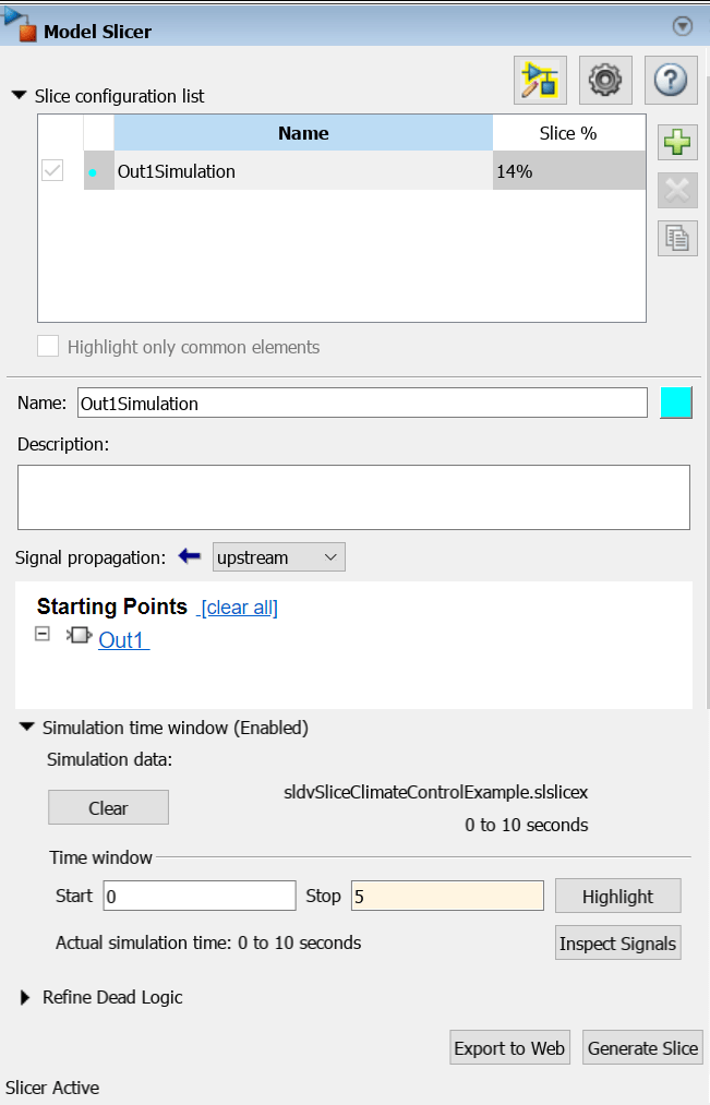
11. To see how this constraint affects the highlighted portion of the model, open the Refrigeration subsystem.
The highlighted portion of the model includes only the input ports of switches that are active in the simulation time window that you specified.
After you refine your highlighted model to include only those blocks used in a portion of a simulation time window, you can then Create a Simplified Standalone Model incorporating the highlighted portion of your model.
Exclude Blocks
You can refine a highlighted model to exclude blocks from the analysis. Excluding a block halts the propagation of dependencies, so that signals and model items beyond the excluded block in the analysis direction are ignored.
Exclusion points are useful for viewing a simplified set of model dependencies. For example, control feedback paths create wide dependencies and extensive model highlighting. You can use an exclusion point to restrict the analysis, particularly if your model has feedback paths.
Note
Simplified standalone model creation is not supported for highlighted models with exclusion points.
In the Model Slicer, click the arrow to expand the Slice configuration list.
To add a new slice configuration, click the add new button
 .
.Set the slice properties:
Name:
Out1ExcludedColor:
 (red)
(red)Signal Propagation:
upstream
In the top level of the model, select the
Out1block as the slice starting point. Right-clickOut1, and in the Model Slicer app section , select Add as Starting Point button
  .
.
The model is highlighted.
To open the subsystem, double-click
Refrigeration.Right-click the
Fanswitch block, and in the Model Slicer app section, select Add as Exclusion Point button  .
.The blocks that are exclusively upstream of the
Fanswitch block are no longer highlighted. TheDT FanData Store Read block is no longer highlighted.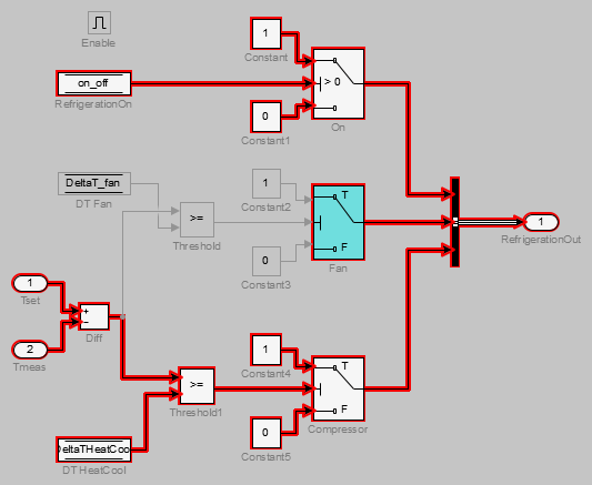
To see how this constraint affects the highlighted portion of the model, view the parent system.
The
DSM fan tempData Store Memory block and theWrite2Data Store Write block are no longer highlighted, because theDT FanData Store Read in theRefrigerationsubsystem no longer accesses them.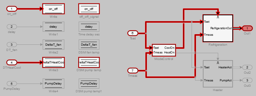
Exclude Inputs of a Switch Block
For complex signal routing, you can constrain the dependency analysis paths to a subset of the available paths through switch blocks. Constraints appear in the Model Slicer. Simplified standalone model creation is not supported for highlighted models with constrained switch blocks.
Double-click
Refrigerationto open the subsystem.Constrain the
Onswitch block:Right-click the switch block and click the Add Constraint button
 .
.In the Constraints dialog box, select Port 3.
Click OK.
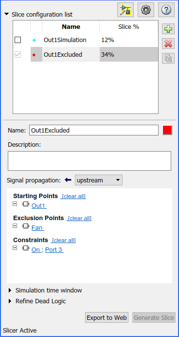
The path is restricted to the
Constant1port on the switch. The blocks that are upstream of Port 1 and Port 2 of the constrained switch are no longer highlighted. Only the blocks upstream of Port 3 are highlighted.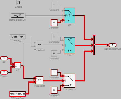
To see how this constraint affects the highlighted portion of the model, view the parent system.