Export Model as FMU with Constant Periodic Clocks
This example shows how to export a Simulink® model, with fixed-step solver, as a standalone cosimulation FMU that is compatible with FMI 3.0 standards and contains constant periodic clocks. During export of a model as FMU, Simulink registers unique discrete periodic sample rates specified in root inport and outport blocks as constant periodic clocks within the FMU. Root inport and outport blocks can also inherit their sample time information.
In the first section of this example, an FMU with constant periodic clocks specified for its interfaces is generated from a Simulink model. In the second section, the FMU is imported back into Simulink for simulation.
Generate FMU with Constant Periodic Clocks
Open the model_pwm model. This model generates a PWM signal based on the specified duty cycle and frequency. For more information about this model, see Implement Block Algorithms Using MATLAB System Object and MATLAB System Block.
model_for_export = 'model_pwm';
open_system(model_for_export);
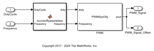
This model has a base sample rate of 1e-4 second. The sample time of the root inport ports are specified as inherited. The model has two outports. The first is set to inherit its sample time information and the second has a specified sample time of 0.01 second and offset of 0.005 second. All sample times are specified by setting the value of Sample time field within the execution tab of the inport block dialog box.

Update the model and check the registered unique discrete periodic sample rates for the model in the timing legend and to see the blocks annotated with its registered sample times. After updating the model, press Ctrl + J to view the timing legend.
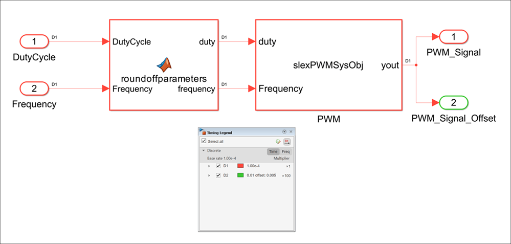
Use the exportToFMU function with ConstantPeriodicClock argument set to on to generate the FMU with clocks. Clock variables are only supported for cosimulation FMUs compatible with FMI 3.0 standards.
exportToFMU(model_for_export,'FMIVersion','3.0','FMUType','CS',...
    'ConstantPeriodicClock','on');
Setting System Target to FMU 'Co-Simulation' for model 'model_pwm'.
Setting Hardware Implementation > Device Type to 'MATLAB Host' for model 'model_pwm'.
### Searching for referenced models in model 'model_pwm'.
### Total of 1 models to build.
### 'GenerateReport' is disabled for 'Co-Simulation' FMU Export.
### 'GenerateComments' is disabled for 'Co-Simulation' FMU Export.

Build Summary

Top model targets:

Model      Build Reason                                         Status                        Build Duration
============================================================================================================
model_pwm  Information cache folder or artifacts were missing.  Code generated and compiled.  0h 0m 22.745s

1 of 1 models built (0 models already up to date)
Build duration: 0h 0m 23.85s
### Model was successfully exported to 'Co-Simulation' FMU: '/tmp/Bdoc25b_2988451_1020324/tpd4a4589a/simulinkcompiler-ex93290521/model_pwm.fmu'.
The modelDescription.xml file of the generated will FMU contain a Clock element defining a clock variable for each identified unique discrete periodic sample rate.
Import and Simulate FMU with Clocks
Open the sim_pwm model that imports the FMU into Simulink and specifies a duty cycle and frequency. Update the model and check the timing legend to see that the FMU registers the clock variables as block sample rates.
model_for_sim = 'sim_pwm';
open_system(model_for_sim);
set_param(model_for_sim,'SimulationCommand','Update');
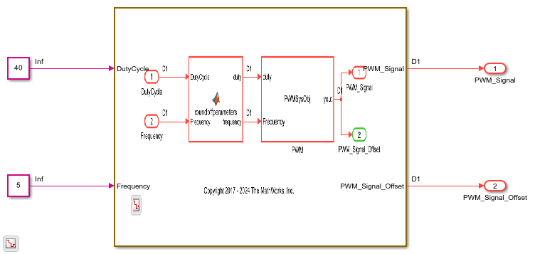
You must enable event mode for the imported FMU to observe the effect of clock variables. To do so, on the FMU Import block dialog box, in the Simulation tab, select Enable event mode option.
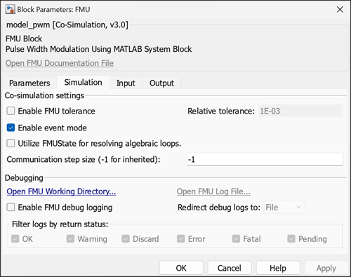
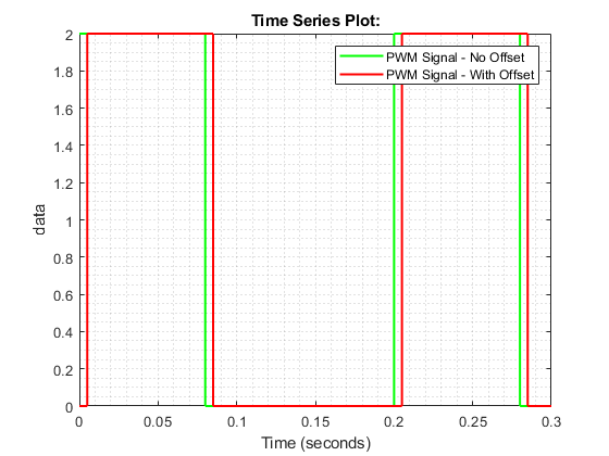
Simulate the sim_pwm model. Observe that the output of the FMU depends on the specified sample rate and offset in the outports. The output value for the second outport is updated according the specified interval of 0.01 second with an offset of 0.005 second.
result = sim(model_for_sim);
figurePlot = figure(1);
plot(result.yout{1}.Values,'g','LineWidth',1.5)
hold on
plot(result.yout{2}.Values,'r','LineWidth',1.5)
hold on
grid minor
xlabel('Time (seconds)')
ylabel('Signal')
legend('PWM Signal - No Offset', 'PWM Signal - With Offset')
