PID Tuning with Reference Tracking and Plant Uncertainty
This example shows how to use Simulink® Design Optimization™ to track a reference signal and optimize the response with uncertainties in the plant model. The plant model consists of the plant transfer function and includes a Saturation block and a Rate Limits block. To view the results, use the following steps.
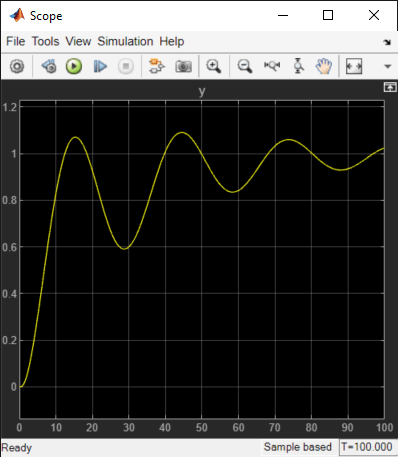
Open the pidtrack_demo model using the command below and run the simulation. The simulation produces an unoptimized step response and the initial data for optimization.
open_system('pidtrack_demo')
![]()
Double-click the Scope block to view the unoptimized step response.

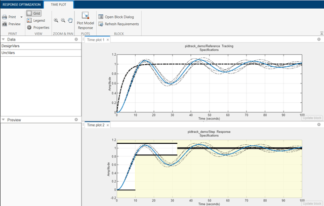
Double-click the Step Response Specifications block to view constraints on the plant response, including rise time, settling time and maximum overshoot.
Double-click the Reference Tracking Specifications block to view the reference signal that the controller has to track.
You can launch the Response Optimizer using the Apps menu in the Simulink toolstrip, or the sdotool command in MATLAB®. You can launch a pre-configured optimization task in the Response Optimizer by first opening the model and by double-clicking on the orange block at the bottom of the model. From the Response Optimizer, press the Plot Model Response button to simulate the model and show how well the initial design satisfies the design requirements.

The solid lines in the plots indicate the plant response without considering the uncertainties and the dashed lines indicate the uncertain responses.
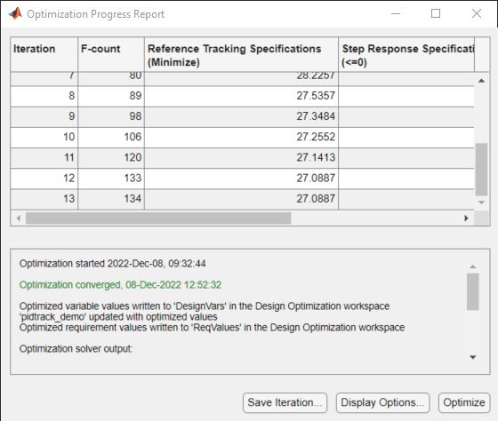
Start the optimization by pressing the Optimize button from the Response Optimizer.
The tuned parameters are the PID Controller gains Kp, Ki, and Kd. The plant parameters a1 and a2 are only known within 10% (uncertainty).
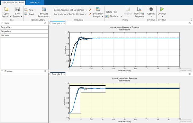
The optimization seeks to minimize the gap between the actual and ideal responses for the nominal values (solid lines) and min/max values (dotted lines) of a1 and a2.
The plots are updated to indicate that the design requirements are now satisfied.

