Set Run in Kernel Mode Code Generation Parameters
After you create a Simulink® model, you can enter simulation parameters. Simulink Coder™ uses these parameters for creating C code and building a real-time application.
This procedure uses the Simulink
Desktop Real-Time™ model sldrtex_model. To open this model, in the
MATLAB® Command Window, type:
openExample('sldrtex_model')It assumes that you have already loaded that model.
In the Simulink Editor, on the Desktop Real-Time tab, click Hardware Settings.
In the Configuration Parameters dialog box, click the Code Generation node.
In the Target selection section, click the Browse button at the System target file list.
In the System target file browser, select the system target file for building a Simulink Desktop Real-Time application,
sldrt.tlc, and click OK.The dialog box enters the system target file
sldrt.tlc, the template makefilesldrt.tmf, and the make commandmake_rtwinto the Code Generation pane.If you have the Embedded Coder® product, you can build an ERT target application. To build an ERT target application, in the Target selection section, click the Browse button at the System target file list. Click
sldrtert.tlc, and then click OK.Although not visible in the Code Generation pane, when you click OK you also configure the external target interface MEX file
sldrtext. This file allows Run in Kernel mode to pass new parameters to the real-time application and to return signal data from the real-time application. The data is displayed in Scope blocks or saved with signal logging.
Do not set Default parameter behavior to
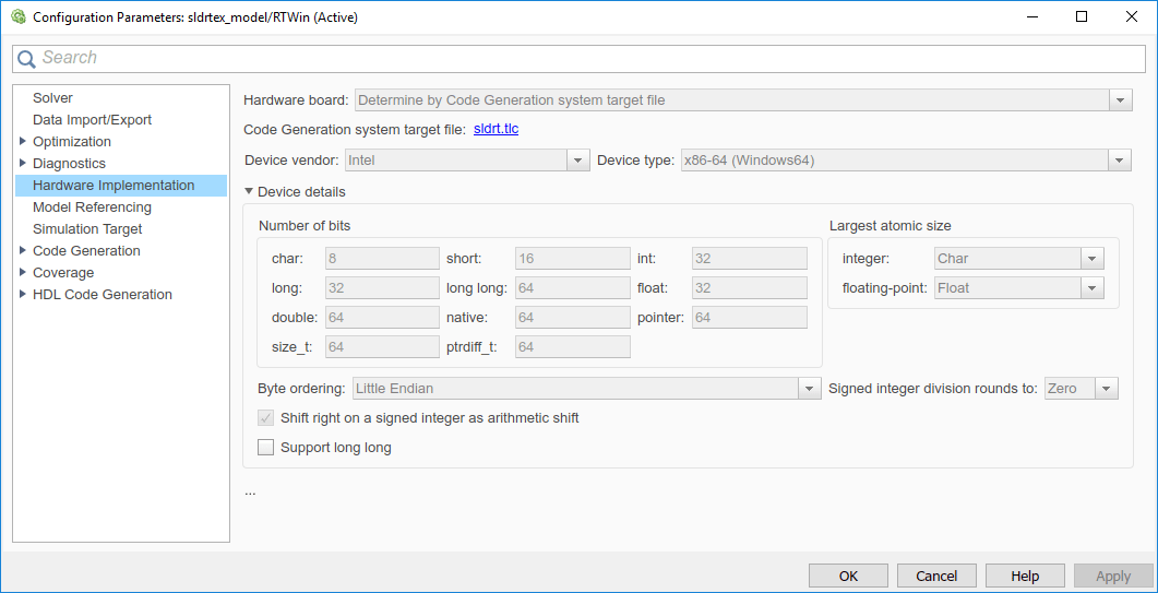
Inlinedon the Optimization node under Code Generation. Inlining parameters is for custom targets when you want to reduce the amount of RAM or ROM with embedded systems. Also, if you select inlining parameters, you disable the parameter tuning feature. Do not inline parameters because PCs have more memory than embedded systems.Click the Hardware Implementation node. The default values are derived from the architecture of the development computer. For example, for a 64-bit Intel® machine, they are:
Device vendor —
IntelDevice type —
x86-64

Click OK.