Main Content

Point

Point geometry for contact modeling

Since R2020b

  • Point Block

Libraries:
Simscape / Multibody / Curves and Surfaces

Description

The Point block exports a 0-D point geometry for modeling contact problems. You can model contacts between the point and many types of geometries, such as all the solids and convex hulls in the Body Element library and the infinite plane in the Curves and Surfaces library. However, you cannot model a contact between a pair of points because there is no penetration, which is necessary for the penalty method, between two points.

Point

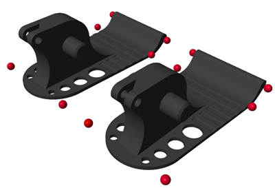
Using the point geometry can simplify and speed up contact modeling that involves complex geometries by eliminating unnecessary geometric details. For example, in the Train Humanoid Walker example, you can simplify the feet-ground contact by using several points to represent the robot feet.

Robot Feet

Ports

Frame

expand all

Local reference frame to use to define the location and orientation of the point.

Geometry

expand all

Geometry frame that represents the point defined by this block. Connect this port to the Spatial Contact Force block to model contacts on the point.

Parameters

expand all

Graphic

Graphic used to visualize the point. Specify this parameter to None to eliminate the point from the model visualization.

Shape of the marker used to visualize the point. The marker shape has no effect on the contact results of the point.

Dependencies

To enable this parameter, set Type to Marker.

Width of the marker in pixels. This width does not scale with zoom level. Note that the apparent size of the marker depends partly on screen resolution, with higher resolutions packing more pixels per unit length, and therefore producing smaller icons.

Dependencies

To enable this parameter, set Type to Marker.

Parameterizations for specifying visual properties. Select Simple to specify diffuse color and opacity. Select Advanced to specify more visual properties, such as Specular Color, Ambient Color, Emissive Color, and Shininess.

Dependencies

To enable this parameter, set Type to Marker.

Color of the graphic under direct white light, specified as an [R G B] or [R G B A] vector on a 0–1 scale. An optional fourth element (A) specifies the color opacity on a scale of 0–1. Omitting the opacity element is equivalent to specifying a value of 1.

Dependencies

To enable this parameter, set Type to Marker.

Graphic opacity, specified as a scalar in the range of 0 to 1. A scalar of 0 corresponds to completely transparent, and a scalar of 1 corresponds to completely opaque.

Dependencies

To enable this parameter, set:

  1. Type to From Geometry or Marker

  2. Visual Properties to Simple

Color of the light due to specular reflection, specified as an [R,G,B] or [R,G,B,A] vector with values in the range of 0 to 1. The vector can be a row or column vector. The optional fourth element specifies the color opacity. Omitting the opacity element is equivalent to specifying a value of 1. This parameter changes the color of the specular highlight, which is the bright spot on the rendered solid due to the reflection of the light from the light source.

Dependencies

To enable this parameter, set:

  1. Type to From Geometry or Marker

  2. Visual Properties to Advanced

Color of the ambient light, specified as an [R,G,B] or [R,G,B,A] vector with values in the range of 0 to 1. The vector can be a row or column vector. The optional fourth element specifies the color opacity. Omitting the opacity element is equivalent to specifying a value of 1.

Ambient light refers to a general level of illumination that does not come directly from a light source. The Ambient light consists of light that has been reflected and re-reflected so many times that it is no longer coming from any particular direction. You can adjust this parameter to change the shadow color of the rendered solid.

Dependencies

To enable this parameter, set:

  1. Type to From Geometry or Marker

  2. Visual Properties to Advanced

Color due to self illumination, specified as an [R,G,B] or [R,G,B,A] vector in the range of 0 to 1. The vector can be a row or column vector. The optional fourth element specifies the color opacity. Omitting the opacity element is equivalent to specifying a value of 1.

The emission color is color that does not come from any external source, and therefore seems to be emitted by the solid itself. When a solid has a emissive color, the solid can be seen even if there is no external light source.

Dependencies

To enable this parameter, set:

  1. Type to From Geometry or Marker

  2. Visual Properties to Advanced

Sharpness of specular light reflections, specified as a scalar number on a 0–128 scale. Increase the shininess value for smaller but sharper highlights. Decrease the value for larger but smoother highlights.

Dependencies

To enable this parameter, set:

  1. Type to From Geometry or Marker

  2. Visual Properties to Advanced

Extended Capabilities

C/C++ Code Generation
Generate C and C++ code using Simulink® Coder™.

Version History

Introduced in R2020b