Model a Cartesian 3-D Printer
R2026bThis example models a Cartesian 3-D printer. In this model, the printer uses Lead Screw Joint blocks to represent the actuators that drive the motion of the printing head along the x-, y-, and z-axes. These lead screw joints convert rotational input into translational motion.
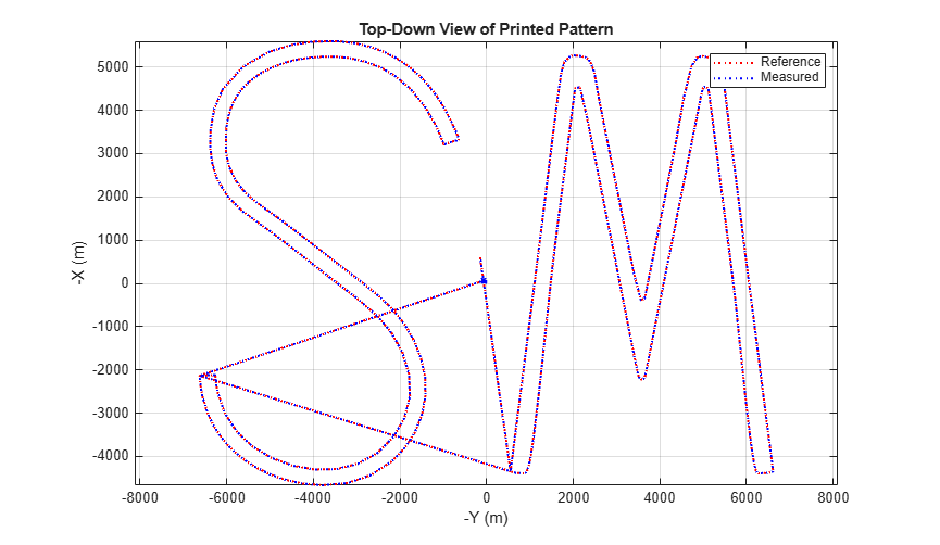
To define the desired motion of the printing head, you specify the target printing path for each axis. A closed-loop controller compares the target printing path with the measured position of the printing head during the simulation. In this example, the printing head target path traces the edges of the letters "S" and "M".
Open the Model
Open the model.
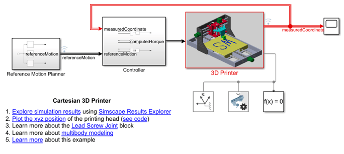
The model contains three subsystems. The Reference Motion Planner subsystem defines the target printing path. The Controller subsystem defines PID controllers for each axis and computes torque commands for the x-, y-, and z-axis actuators. The 3-D Printer subsystem defines the geometry, actuators, and degrees of freedom of the printer.
Examine the 3D Printer Subsystem
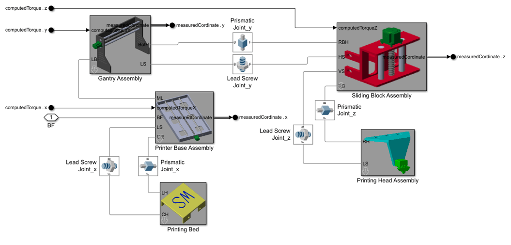
The 3D Printer subsystem has three degrees of freedom and contains the Gantry Assembly, Sliding Block Assembly, Printer Base Assembly, Printing Bed, and Printing Head Assembly subsystems. The prismatic and lead screw joints constrain the subsystems and permit movements along x-, y-, and z-axes.
The 3D Printer subsystem uses the external torque computed from the Controller subsystem as the motion input to each axis in order to drive the printing head.
Simulate the Model
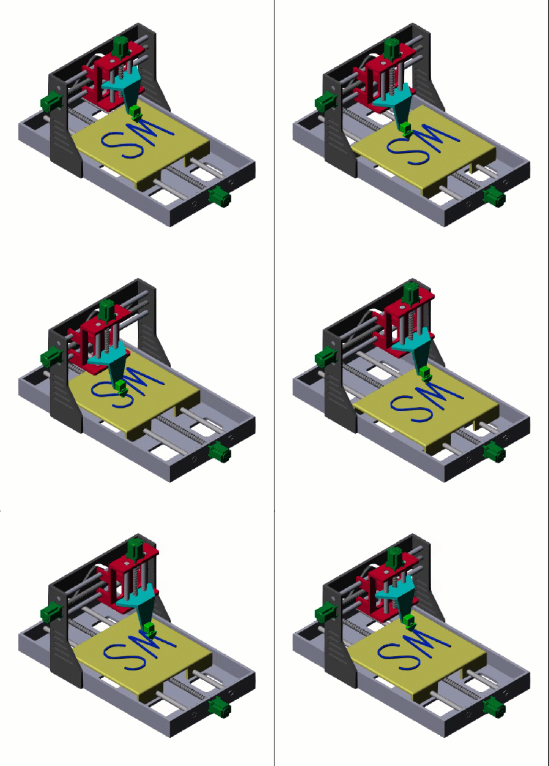
Simulate the model and view the resulting animation in the Multibody Explorer.
Simulation Results
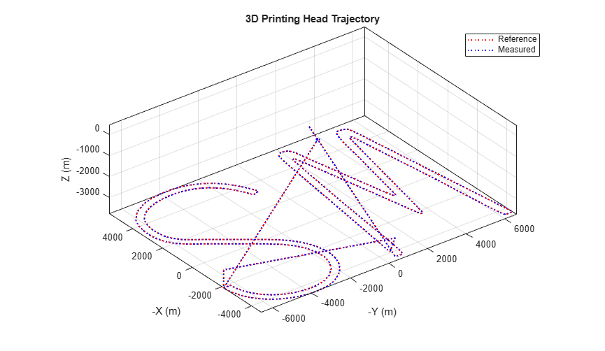
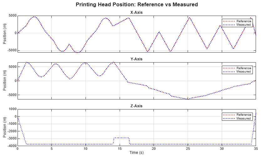
Click the Plot the xyz position link to create plots comparing the reference and measured x -, y -, and z-positions of the printing head during printing. Notice how the measured position accurately tracks the reference position.
See Also
Lead Screw Joint | Revolute Joint

