Hardware-Software Partitioning of a Motor Control Algorithm
This example shows how to model a motor controller for SoC devices by partitioning the control and calibration algorithms between the FPGA and processor of the SoC.
Introduction
This example shows how to partition a Field-Oriented Controller (FOC) for a Permanent Magnet Synchronous Motor (PMSM) onto an SoC device. The following diagram shows a conceptual closed-loop FOC of PMSM.

In an FOC running in closed-loop, the current control loop needs to run at a high rate, typically microseconds. In contrast, the velocity control can run at lower rates, typically milliseconds, but must react to external events, such as commanded velocity updates. By partitioning the current and velocity controllers onto the FPGA and processor cores, respectively, both control loops in the FOC can meet the above requirements.
The first model in this example is used for behavioral simulation of a closed-loop FOC with an open-loop calibration controller for a PMSM. The second model shows how the open-loop calibration controller, closed-loop velocity controller, and closed-loop current controller can be partitioned into an SoC device using SoC Blockset. A comparison of the simulation results between the behavioral and SoC models shows the expected behavior of the controller is maintained.
Behavioral Model
The top-level structure of the behavioral model is shown below. The Plant subsystem models a PMSM with load with simulated measurements from a motor shaft encoder and current sensors. The model parameters of the motor, load, and sensors are based on the AD-FMCMOTCON2-EBZ Evaluation Board from Analog Devices®. The Controller subsystem contains the closed-loop FOC and the open-loop calibration controllers.

The Controller is split into two subsystems, an inner Current Control loop and outer Velocity and Calibration Control loop.
The Current Control subsystem takes a command current value from the Calibration and Velocity Control subsystem. The current controller uses consecutive Clarke and Park transforms to convert the AC current and voltage waveform into DC signals. A Proportional-Integral (PI) controller uses the DC signals to drive PWM switching signals to the power MOSFETs driving the PMSM.
The Velocity Control subsystem takes external commands to set the mode of the controller as either calibrating or closed-loop velocity tracking. In the calibration mode, the Mode_Scheduler spins the motor using an open-loop velocity controller to identify the zero index of the shaft encoder. Then the controller commands and holds a zero position to identify the encoder offset. After determining the encoder offset, the velocity controller is calibrated and can be switched into closed-loop velocity control. The closed-loop velocity control also uses a PI controller, similar to the current controller.
Hardware-Software Partitioned SoC Model
The structure of the partitioned SoC model is based on the partitioning scheme shown below. The fast current controller is running on the FPGA and the slow velocity controller on the processor. The FPGA and processor communicate via AXI interface.

The original Controller subsystem from the behavioral model has been partitioned into the processor and FPGA models, which are connected with Register Channel blocks.

Processor
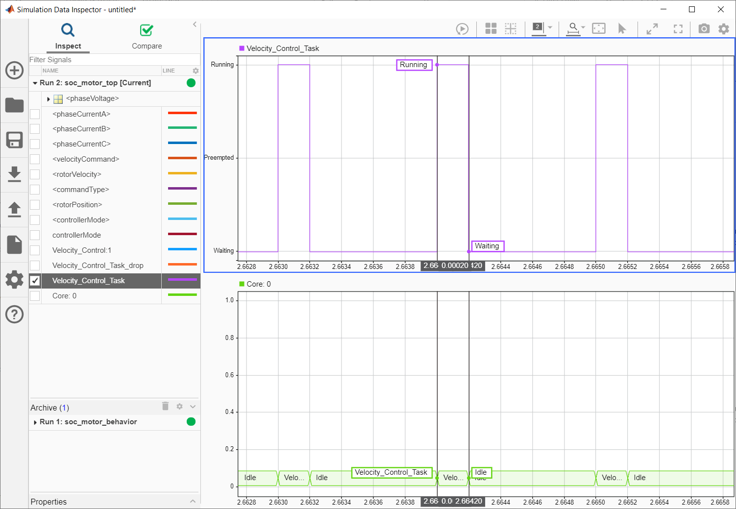
The open-loop calibration and the closed-loop velocity controllers are now inside a Model block and operate as a task driven by the Task Manager block. As part of the task iteration, the controller first reads from the AXI registers using Register Read blocks, iterates the control algorithm, and then writes the updated outputs to the AXI register using the Register Write blocks. The Task Manager executes the controller task at a rate of 1kHz with an average execution duration of 0.2ms.
AXI Interface
Register Channel block models the AXI communication between FPGA and Processor for register read and write operations. The corresponding AXI4-Lite driver blocks, Register Read/Register Write, are used in Processor Model to represent AXI4-Lite interface.
FPGA
The closed-loop current controller is contained in the Model block representing the FPGA of the SoC device. Since the current controller exists in the FPGA, it can write and read directly from the AXI hardware registers. The FPGA uses a 40us clock.
Comparison of Behavioral and SoC Model Simulations
1. Open and run the behavioral model. Observe the controller and motor behavior from the System_Response scope.

2. Open and run the partitioned SoC model. Observe that the controller and motor behavior matches.
3. Click Data Inspector to open the Simulation Data Inspector (SDI). Signal data for the previous model runs was automatically captured and archived in the SDI.
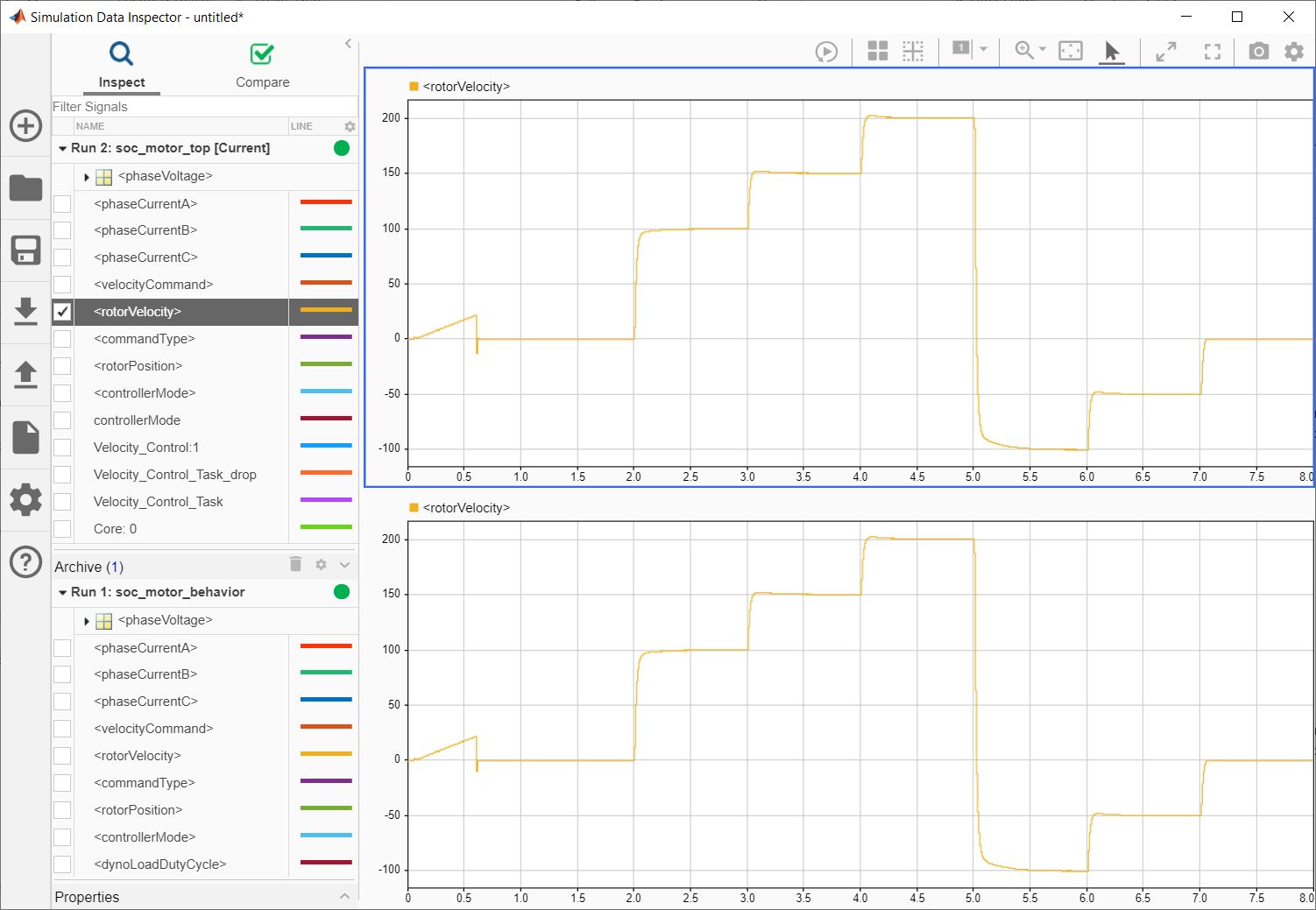
4. Select the rotorVelocity from Run 1: soc_motor_behavior and the rotorVelocity from Run 2: soc_motor_top into each subplot to get the following plot. Both the behavioral and partitioned models demonstrate equivalent motor velocity tracking.

5. From Run 2: soc_motor_top, select and display the Velocity_Control_Task and Core: 0 signals into each subplot to get the following plot. From the plot, you can observe the task execution time of the velocity controller and the CPU utilization.

Implement on Hardware
You can implement this motor control design on Trenz Electronic Motor Control Development Kit, based on Xilinx® Zynq® UltraScale+ MPSoC. To see an example go to Implement Field-Oriented Control on FPGA SoC.