Integrated Circuits
使用放大器、振荡器、计时器和计数器对常用集成电路进行建模。通过组合布尔函数产生单个逻辑输出。
精选示例
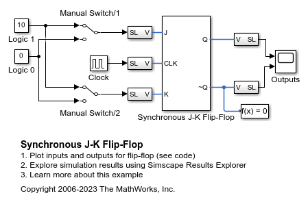
Synchronous J-K Flip-Flop
Model a J-K flip-flop from Simscape™ Electrical™ logic components. With the two switches in their default positions, both inputs to the flip-flop are set high so its output state toggles each time the clock signal goes low. Initial conditions are passed to the relevant NAND gates via the initialization commands of the block mask.
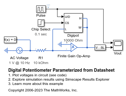
Digital Potentiometer Parameterized from Datasheet
How to model a digital potentiometer such as is used to control audio amplifiers from a digital circuit or microprocessor-controlled system. The model also shows how you can create your own custom blocks in order to extend the Simscape™ Electrical™ library.

含噪运算放大器建模
此示例展示了如何在电气仿真中加入噪声。该电路对了一个高频滚降频率为 10 MHz 的放大器进行了建模。Band-Limited Op-Amp 模块用于添加噪声。Voltage Source 模块 Vn 指定等效电压噪声密度为 20 nV/Hz^0.5。您还可以通过将两个 Resistor 模块的噪声模式参数设置为 Enabled 来添加来自电阻器 R1 和 R2 的热噪声。但是,通过使用不同的噪声源组合运行此模型,可以看到主要的噪声源是等效噪声电压。
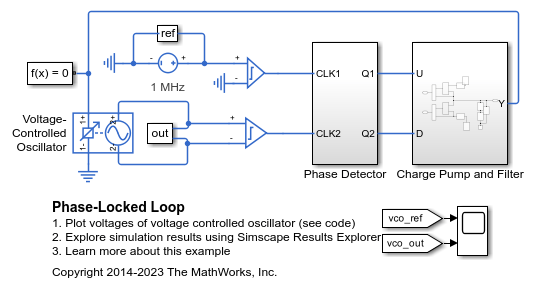
锁相环
此示例展示了如何对锁相环进行建模。电荷泵和滤波器使用离散模拟元件进行建模,而振荡器则使用 Simscape™ Electrical™ Voltage-Controlled Oscillator 模块表示为行为组件。相位检测器中的 D 型触发器使用 Simulink® 模块以简化形式表示,以便定义行为,并且仅在接口处使用电气元件。对 C1 和 C2 应用非零初始条件,以便异相启动 VCO 并测试跟踪能力。

使用 PWM 电压源和 H 桥驱动器控制 DC 电机
此示例展示了如何使用 Controlled PWM Voltage 和 H-Bridge 模块来控制 DC 电机。DC Motor 模块在 2500 rpm 转速下提供 10 W 的机械功率,并且在 DC 电源电压为 12 V 时以 4000 rpm 的空载转速运行。因此,如果将 PWM 参考电压设置为其最大值 5 V,电机将以 4000 rpm 的转速运行。如果将 PWM 参考电压设置为 2.5 V,电机将以约 2000 rpm 的转速运行。为了实现快速仿真,此示例将 Controlled PWM Voltage 模块和 H-Bridge 模块的仿真模式参数设置为 Averaged。要验证平均行为,请在 Controlled PWM Voltage 模块和 H-Bridge 模块中将 Simulation mode 参数都设置为 PWM。
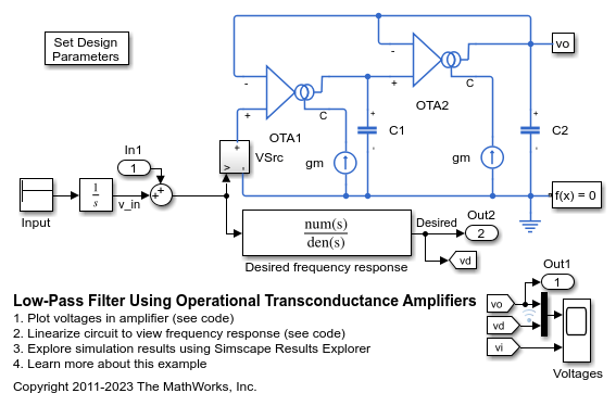
Low-Pass Filter Using Operational Transconductance Amplifiers
Model a second-order active low-pass filter. The filter is characterized by the transfer function H(s) = 1 / ( (s/w1)^2 + (1/Q)*(s/w1) + 1 ) where w1 = 2*pi*f1, f1 is the cut-off frequency and Q is the quality factor. Double-click on the Set Design Parameters block to set parameters f1 and Q. The block mask calls a function which sets the parameter values in the model workspace.
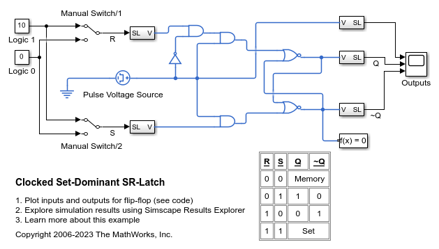
Clocked Set-Dominant SR-Latch
Model a Set-dominant SR-Latch from Simscape™ Electrical™ logic components. Initial conditions are passed to the relevant AND gates via the initialization commands of the switches.

Clocked Reset-Dominant SR-Latch
Model a Reset-dominant SR-Latch from Simscape™ Electrical™ logic components. Initial conditions are passed to the relevant AND gates via the initialization commands of the switches.