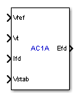
AC1A Excitation System
(To be removed) Implements IEEE type AC1A excitation system model
The Specialized Power Systems library will be removed in R2026a. Use the Simscape™ Electrical™ blocks and functions instead. For more information on updating your models, see Upgrade Specialized Power System Models to use Simscape Electrical Blocks.
Library
Simscape / Electrical / Specialized Power Systems / Electrical Machines / Synchronous Machine Control
Description
This block models an ac alternator driving a diode rectifier to produce the field voltage Vf required by the Synchronous Machine block. A non-controlled voltage regulator provides a voltage in p.u. with a lower limit of zero imposed by the diode rectifier.
This block is an adaptation of the AC1A excitation system of the IEEE® 421 standard, copyright IEEE 2005, all rights reserved.
Parameters
Controllers Tab
- Low-pass filter time constant
The time constant Tr of the first-order system representing the stator terminal voltage transducer. Default is
20e-3.- Voltage regulator gain and time constant
The gain Ka and time constant Ta of the first-order system representing the main regulator. Default is
[400 0.02].- Voltage regulator internal limits
The voltage regulator internal limits VAmin and VAmax, in p.u. Default is
[-14.5 14.5].- Voltage regulator output limits
The voltage regulator output limits VRmin and VRmax, in p.u. Default is
[-5.43 6.03].- Damping filter gain and time constant
The gain Kf and time constant Tf of the first-order system representing the derivative feedback. Default is
[0.03 1.0].- Transient gain reduction lead and lag time constants
The time constants Tb and Tc of the first-order system representing the lead-lag compensator. Default is
[0 0].
Exciter and Rectifier Tab
- Exciter gain and time constant
The gain Ke and time constant Te of the first-order system representing the exciter. Default is
[1.0 0.80].- Exciter alternator voltage values
The exciter saturation function is defined as a multiplier of exciter alternator output voltage to represent the increase in exciter excitation requirements due to saturation [1]. The saturation function is determined by specifying two voltage points,Ve1 and Ve2 in p.u., on the air-gap line and no-load saturation curve and providing the corresponding two saturation multipliers SeVe1 and SeVe2. Default is
[4.18 3.14].Typically, the voltage Ve1 is a value near the expected exciter maximum output voltage, Ve2 value is about 75% of Ve1 [1].
- Exciter saturation function values
The exciter saturation function is defined as a multiplier of exciter alternator output voltage to represent the increase in exciter excitation requirements due to saturation [1]. The saturation function is determined by specifying two voltage points, Ve1 and Ve2 in p.u., on the air-gap line and no-load saturation curve and providing the corresponding two saturation multipliers SeVe1 and SeVe2. Default is
[0.10 0.03].SeVe1 and SeVe2 multipliers are equal to C-B / B, C is the value of exciter field current on the no-load saturation curve corresponding to the specified Ve voltage, and B is the value of exciter field current on the air-gap line corresponding to the selected Ve voltage [1].
If you do not want to model the saturation effect, set SeVe1 and SeVe2 values to zero.
- Demagnetizing factor Kd
The gain Kd represents the demagnetizing factor, a function of exciter alternator reactances. Default is
0.38.- Rectifier loading factor Kc
The gain Kc represents the rectifier loading factor proportional to the commutating reactance. Default is
0.20.
Initial Values Tab
- Initial values of terminal voltage and field voltage
The initial values of terminal voltage Vt0 and field voltage Efd0, both in p.u. Initial terminal voltage is normally set to 1 pu. The Vt0 and Efd0 values can be determined using the Powergui Load Flow tool. Default is
[1 1].- Sample time
Specify a value greater than zero to discretize the block at the given sample time. Set to -1 to inherit the simulation type and sample time parameters of the Powergui block. Default is
0.
Ports
- Vref
The reference value of the stator terminal voltage, in p.u.
- Vt
The measured value in p.u. of the stator terminal voltage of the controlled Synchronous Machine block.
- Ifd
The measured value in p.u. of the stator field current of the controlled Synchronous Machine block.
- Vstab
Connect this input to a power system stabilizer to provide additional stabilization of power system oscillations. When you do not use this option, connect to a Simulink® ground block. The input is in p.u.
- Efd
The field voltage to apply to the
Vfinput of the controlled Synchronous Machine block. The output is in p.u.
References
[1] “IEEE Recommended Practice for Excitation System Models for Power System Stability Studies.” IEEE Standard, Vol. 421, No. 5, 2005 (Revision of IEEE 521.5-1992).
Version History
Introduced in R2012b
