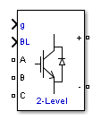
Two-Level Converter
Implement three-phase two-level power converter
Library
Simscape / Electrical / Specialized Power Systems / Power Electronics
Description
The Two-Level Converter block implements a three-phase, two-level power converter. You can choose from four model types:
Switching devices
— The converter is modeled with IGBT/diode pairs controlled by firing pulses produced by a PWM generator. This model provides the most accurate simulation results.Switching function
— The converter is modeled by a switching-function model. The switches are replaced with two voltage sources and two diodes on the AC side and with two current sources on the DC side.The converter is controlled by firing pulses produced by a PWM generator (0/1 signals) or by firing pulses averaged over a specified period (PWM averaging: signals between 0 and 1). Both modes of operation produce harmonics normally generated by a PWM-controlled converter and also correctly simulate rectifying operation as well as blanking time. This model type is well-suited for real-time simulation.
Average model (Uref-controlled)
— The converter is modeled using a switching-function model directly controlled by the reference voltage signals (Uref). A PWM generator is not required.Average model (Uref-controlled, no rectifier mode)
— The block uses the voltage source directly controlled by the reference voltage to model the converter. The model does not require a PWM generator and does not simulate the rectifier mode.When doing real-time simulation, use the
Switching function
setting with the firing pulses averaged, or theAverage model (Uref-controlled)
orAverage model (Uref-controlled, no rectifier mode)
settings.
Parameters
- Model type
Select one of these values:
Switching devices
(default)Switching function
Average model (Uref-controlled)
Average model (Uref-controlled, no rectifier mode)
- Device on-state resistance (Ohms)
Internal resistance of the switching devices, in ohms. This parameter is available only when you set the Model type parameter to
Switching devices
. The default value is1e-3
.- Snubber resistance (Ohms)
The snubber resistance, in ohms. Set the snubber resistance to
inf
to eliminate the snubbers. This parameter is available only when you set the Model type parameter toSwitching devices
. The default value is1e6
.- Snubber capacitance (F)
The snubber capacitance, in farads. Set the snubber capacitance to
0
to eliminate the snubbers. This parameter is available only when you set the Model type parameter toSwitching devices
. The default value isinf
.- Diode on-state resistance (Ohms)
Internal resistance of the diodes, in ohms. This parameter is available only when you set the Model type parameter to
Switching function
orAverage model (Uref-controlled)
. The default value is1e-3
.- Diode snubber resistance (Ohms)
The snubber resistance, in ohms. Set the snubber resistance to
inf
to eliminate the snubbers. This parameter is available only when you set the Model type parameter toSwitching function
orAverage model (Uref-controlled)
. The default value is1e6
.- Diode snubber capacitance (F)
The snubber capacitance in farads. Set the snubber capacitance to
0
to eliminate the snubbers. This parameter is available only when you set the Model type parameter toSwitching function
orAverage model (Uref-controlled)
. The default value isinf
.- Diode forward voltage (V)
Forward voltage, in volts, across the diode when it is conducting. This parameter is available only when you set the Model type parameter to
Switching function
orAverage model (Uref-controlled)
. The default value is1e-3
.- Current source snubber resistance (Ohms)
The snubber resistance across the two current sources, in ohms. Set the snubber resistance to
inf
to eliminate the snubbers. This parameter is available only when you set the Model type parameter toSwitching function
orAverage model (Uref-controlled)
. The default value isinf
.
Inputs and Outputs
g
A vectorized gating signal to control the converter. The gating signal contains six firing pulses. The first two pulses control the Q1 and Q2 switching devices (phase A of the converter), pulses three and four control the Q3 and Q4 switching devices (phase B of the converter), and the last two pulses control the Q5 and Q6 switching devices (phase C of the converter). This port is visible only when you set the Model type parameter to
Switching devices
orSwitching function
.Uref
A vectorized signal to control the converter. The signal contains three reference voltages (one for each phase). This port is visible only when you set the Model type parameter to
Average model (Uref-controlled)
.BL
You can block all firing pulses to the converter by applying a signal value of 1 at the BL input.
Examples
See the Power Converters Modeling Techniques example for a comparison of the three converter modeling techniques.
Version History
Introduced in R2015b