Main Content

Coupled Lines (Pair)

Magnetically couple two lines

  • Coupled Lines (Pair) block

Libraries:
Simscape / Electrical / Passive / Lines

Description

The Coupled Lines (Pair) block models two magnetically coupled lines. Each line has a self-inductance, series resistance, and parallel conductance. In addition, there is a mutual inductance and mutual resistance between the two lines.

Use this block when the magnetic coupling between the two lines is nonnegligible. These effects are most prominent when:

  • The lines are parallel and close together.

  • The self-inductances of the lines are high.

  • The AC frequency of the network is high.

To model magnetic coupling of a three-phase line, use the Coupled Lines block.

Equivalent Circuit

The figure shows the equivalent circuit for a pair of coupled lines.
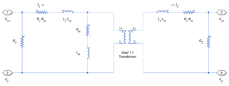
Here:

  • R1 and R2 are the series resistances of lines 1 and 2, respectively.

  • L1 and L2 are the self-inductances of lines 1 and 2, respectively.

  • Rm is the mutual resistance between the two lines. You can use this parameter to account for losses in a common return path.

  • Lm is the mutual inductance between the two lines.

  • G1 and G2 are the leakage conductances of lines 1 and 2, respectively.

  • V1 and V2 are voltage drops across lines 1 and 2, respectively.

  • I1 and I2 are the currents through the resistors R1-Rm and R2-Rm, respectively.

Equations

The defining equation for this block is:

V=[R1RmRmR2]I+[L1LmLmL2]dIdt,

where:

V=[V1V2],

I=[I1I2].

I1 and I2 are, in general, not equal to the currents in line 1 and line 2. These terminal currents make up the vector:

Itotal=I+[G100G2]V.

Inductive Coupling

To quantify the strength of the coupling between the two lines, you can use a coupling factor or coefficient of coupling k. The coupling factor relates the mutual inductance to the line self-inductances:

Lm=kL1L2.

This coupling factor must fall in the range 1<k<1, where a negative coupling factor indicates a reversal in orientation of one of the coils. The magnitude of k indicates:

  • |k|=0 — There is no magnetic coupling between the two lines.

  • 0<|k|<0.5 — The two lines are loosely coupled and mutual magnetic effects are small.

  • 0.5|k|<1 — The two lines are strongly coupled and mutual magnetic effects are large.

Mutual Resistance

If the two lines share a common return path, you can model the resistance of this return path using the Mutual resistance parameter. This workflow is equivalent to setting the Mutual resistance to zero and explicitly modeling the return path resistance Rm, as shown in this diagram.

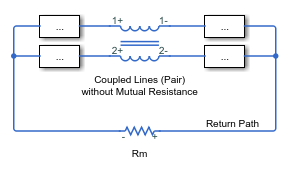
If the two lines do not share a common return path, set the mutual resistance parameter to zero and model each of the return resistances explicitly.

Ports

Conserving

expand all

Electrical conserving port associated with the positive terminal of line 1.

Electrical conserving port associated with the negative terminal of line 1.

Electrical conserving port associated with the positive terminal of line 2.

Electrical conserving port associated with the negative terminal of line 2.

Parameters

expand all

Parameters

Specify how to parameterize the impedance of the two lines:

Balanced impedance

Specify the same series resistance, series inductance, and parallel leakage conductance for both lines.

General impedance

Specify the series resistance, series inductance, and parallel leakage conductance separately for each line.

Self-inductance of line 1. This value must be greater than zero.

Dependencies

To enable this parameter, set Parameterization to General impedance.

Self-inductance of line 2. This value must be greater than zero.

Dependencies

To enable this parameter, set Parameterization to General impedance.

Self-inductance of line 1 and line 2. This value must be greater than zero.

Dependencies

To enable this parameter, set Parameterization to Balanced impedance.

Mutual inductance between line 1 and line 2. If you know the coupling factor, set this value to kL1L2. To have a physically realizable mutual inductance, this value must satisfy:

L1L2<Lm<L1L2.

Series resistance of line 1. This value must be greater than or equal to zero.

Dependencies

To enable this parameter, set Parameterization to General impedance.

Series resistance of line 2. This value must be greater than or equal to zero.

Dependencies

To enable this parameter, set Parameterization to General impedance.

Series resistance of line 1 and line 2. This value must be greater than or equal to zero.

Dependencies

To enable this parameter, set Parameterization to Balanced impedance.

Mutual resistance between line 1 and line 2. This value must be greater than or equal to zero. Use this value to account for losses in a common return path.

Parallel leakage conductance of line 1. This value must be greater than or equal to zero.

Dependencies

To enable this parameter, set Parameterization to General impedance.

Parallel leakage conductance of line 2. This value must be greater than or equal to zero.

Dependencies

To enable this parameter, set Parameterization to General impedance.

Parallel leakage conductance of line 1 and line 2. This value must be greater than or equal to zero.

Dependencies

To enable this parameter, set Parameterization to Balanced impedance.

Extended Capabilities

C/C++ Code Generation
Generate C and C++ code using Simulink® Coder™.

Version History

Introduced in R2018a