Solenoid
Electrical characteristics and generated force of solenoid
Libraries:
Simscape /
Electrical /
Electromechanical /
Mechatronic Actuators
Description
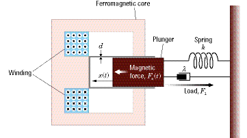
The Solenoid block represents the electrical characteristics and generated force for the solenoid in this figure:

Both positive and negative currents generate a force that pulls the plunger towards the winding. This minimizes the reluctance and decreases the stroke. To increase the stroke, a spring or an external force must overcome the magnetic force.
The return spring is optional. To remove the effects of this spring from the model,
set the Spring constant parameter to 0.
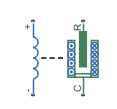
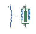
To show the direction in which the solenoid acts, the block icon changes dynamically based on value of the Motion direction under excitation parameter.
Note
If you place an external position sensor around the block, pay attention to the sensor orientation and the initial position condition. The initial position condition you specify on the sensor corresponds to the Stroke, X variable of the Solenoid block only if you orientate the sensor in a direction that is consistent with the value of the Motion direction under excitation parameter.
| When The Motion direction under excitation Parameter Is Set To... | Block Icon |
|---|---|
Port R moves away from port C
|
|
Port R moves towards port
                            C
|
|
The equation of motion for the plunger as a function of position, x, is:
where Fe is the electromagnetic force, Fl is the load force, λ is the viscous damping term and m is the plunger mass. The electromagnetic force is related to the solenoid current and inductance by:
The inductance, which is derived in [1], can be written as:
where α and β are constants. Plugging the preceding equation into the equation for electromagnetic force gives the force-stroke relationship of the solenoid for a current i0:
The Solenoid block solves for α and β by taking the two specified force and stroke measurements and substituting them into the preceding equation. It solves the resulting equations for α and β.
A positive current from the electrical + to - ports creates a negative force (i.e., a pulling force) from the mechanical C to R ports.
Model Thermal Effects
You can expose the thermal port to model the effects of losses that convert power to heat. To expose the thermal port, set the Modeling option parameter to either:
No thermal port— The block does not contain a thermal port.Show thermal port— The block contains one thermal conserving port.
For more information about using thermal ports in actuator blocks, see Simulating Thermal Effects in Rotational and Translational Actuators.
Variables
To set the priority and initial target values for the block variables before simulation, use the Initial Targets section in the block dialog box or Property Inspector. For more information, see Set Priority and Initial Target for Block Variables.
Use nominal values to specify the expected magnitude of a variable in a model. Using system scaling based on nominal values increases the simulation robustness. Nominal values can come from different sources. One of these sources is the Nominal Values section in the block dialog box or Property Inspector. For more information, see System Scaling by Nominal Values.
Use the Stroke, X variable to set the target for the initial plunger position at the start of simulation.
Note
The Stroke, X variable is the initial air gap or
stroke of the solenoid, and so should be greater than or equal to
0.
Examples
Ports
Conserving
Parameters
References
[1] S.E. Lyshevski. Electromechanical Systems, Electric Machines, and Applied Mechatronics. CRC, 1999.
Extended Capabilities
Version History
Introduced in R2008a


