Wye-Connected Load
Three-phase load wired in wye configuration
Libraries:
Simscape /
Electrical /
Passive /
RLC Assemblies
Description
The Wye-Connected Load block models a three-phase load wired in a wye configuration. Each limb of the load can include any combination of a resistor (R), capacitor (C), and inductor (L), connected in series or in parallel.
You can specify values for the R, L, and C components directly in terms of resistance, inductance, and capacitance, or by rated powers at a rated voltage and frequency.
If you parameterize the block directly in terms or R, L, and C values, then for initialization, provide a three-element row vector of initial voltages for a capacitor, and a three-element row vector of initial currents for an inductor.
If you parameterize the block in terms of rated powers, then specify initial conditions in terms of an initial voltage, initial voltage phase, and initial frequency. For example, if the load is connected directly to a three-phase voltage source, then the initial conditions are identical to the source values for RMS line voltage, frequency, and phase shift. To specify zero initial-voltage magnitude, set the initial voltage to
0.
For certain combinations of R, L, and C, for some circuit topologies, you should specify parasitic resistance or conductance values that help the simulation to converge numerically. These parasitic terms help create a small parallel resistive path for an inductor and a small series resistance for a capacitor. When you parameterize the block in terms of rated powers, the rated power values do not account for these small parasitic terms. The rated powers represent only the R, L, and C values of the load itself.
Block Parameterization
These tables list the block parameters for each value of the Component structure parameter, based on the Parameterization option you select:
Specify by rated power and voltageSpecify component values directly
Specify by Rated Power and Voltage
| Component Structure | Main Parameters | Parasitics Parameters | Initial Conditions Parameters |
|---|---|---|---|
| Rated voltage Real power | None | None |
| Rated voltage Rated electrical frequency Inductive reactive power | Parasitic parallel conductance | Terminal voltage magnitude Terminal voltage angle Frequency |
| Rated voltage Rated electrical frequency Capacitive reactive power | Parasitic series resistance | Terminal voltage magnitude Terminal voltage angle Frequency |
| Rated voltage Rated electrical frequency Real power Inductive reactive power | Parasitic parallel conductance | Terminal voltage magnitude Terminal voltage angle Frequency |
| Rated voltage Rated electrical frequency Real power Capacitive reactive power | None | Terminal voltage magnitude Terminal voltage angle Frequency |
| Rated voltage Rated electrical frequency Inductive reactive power Capacitive reactive power | Parasitic parallel conductance | Terminal voltage magnitude Terminal voltage angle Frequency |
| Rated voltage Rated electrical frequency Real power Inductive reactive power Capacitive reactive power | Parasitic parallel conductance | Terminal voltage magnitude Terminal voltage angle Frequency |
| Rated voltage Rated electrical frequency Real power Inductive reactive power | None | Terminal voltage magnitude Terminal voltage angle Frequency |
| Rated voltage Rated electrical frequency Real power Capacitive reactive power | Parasitic series resistance | Terminal voltage magnitude Terminal voltage angle Frequency |
| Rated voltage Rated electrical frequency Inductive reactive power Capacitive reactive power | Parasitic series resistance | Terminal voltage magnitude Terminal voltage angle Frequency |
| Rated voltage Rated electrical frequency Real power Inductive reactive power Capacitive reactive power | Parasitic series resistance | Terminal voltage magnitude Terminal voltage angle Frequency |
Specify Component Values Directly
| Component Structure | Main Parameters | Parasitics Parameters | Initial Targets Variables |
|---|---|---|---|
| Resistance | None | None |
| Inductance | Parasitic parallel conductance | Initial inductor current [ Ia Ib Ic ] |
| Capacitance | Parasitic series resistance | Initial capacitor voltage [ Va Vb Vc ] |
| Resistance Inductance | Parasitic parallel conductance | Initial inductor current [ Ia Ib Ic ] |
| Resistance Capacitance | None | Initial capacitor voltage [ Va Vb Vc ] |
| Inductance Capacitance | Parasitic parallel conductance | Initial inductor current [ Ia Ib Ic ] Initial capacitor voltage [ Va Vb Vc ] |
| Resistance Inductance Capacitance | Parasitic parallel conductance | Initial inductor current [ Ia Ib Ic ] Initial capacitor voltage [ Va Vb Vc ] |
| Resistance Inductance | None | Initial inductor current [ Ia Ib Ic ] |
| Resistance Capacitance | Parasitic series resistance | Initial capacitor voltage [ Va Vb Vc ] |
| Inductance Capacitance | Parasitic series resistance | Initial inductor current [ Ia Ib Ic ] Initial capacitor voltage [ Va Vb Vc ] |
| Resistance Inductance Capacitance | Parasitic series resistance | Initial inductor current [ Ia Ib Ic ] Initial capacitor voltage [ Va Vb Vc ] |
Faults
Since R2024b
To model a fault in the Wye-Connected Load block, in the Faults section, click Add fault next to the fault that you want to model. For more information about fault modeling, see Fault Behavior Modeling and Fault Triggering.
The Wye-Connected Load block allows you to model these types of fault at the three-phase connection port:
Single-phase-to-ground fault (a-g, b-g, or c-g)
Two-phase fault (a-b, b-c, or c-a)
Two-phase-to-ground fault (a-b-g, b-c-g, or c-a-g)
Three-phase fault (a-b-c)
Three-phase-to-ground fault (a-b-c-g)
Variables
To set the priority and initial target values for the block variables prior to simulation, use the Initial Targets section in the block dialog box or Property Inspector. For more information, see Set Priority and Initial Target for Block Variables.
Nominal values provide a way to specify the expected magnitude of a variable in a model. Using system scaling based on nominal values increases the simulation robustness. Nominal values can come from different sources, one of which is the Nominal Values section in the block dialog box or Property Inspector. For more information, see System Scaling by Nominal Values.
For this block, the Initial Targets and Nominal
Values settings are visible only if, in the Main
section, you set the Parameterization parameter to
Specify component values directly and you do not set
the Component structure parameter to
R.
Examples
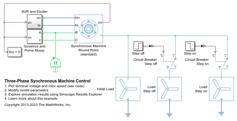
Three-Phase Synchronous Machine Control
Control and initialize a Synchronous Machine (SM). The test circuit shows the SM operating as a generator. The terminal voltage is controlled using an AVR and the speed is controlled using a governor.

Three-Phase Asynchronous Wind Turbine Generator
Model an induction machine used as a wind turbine generator.
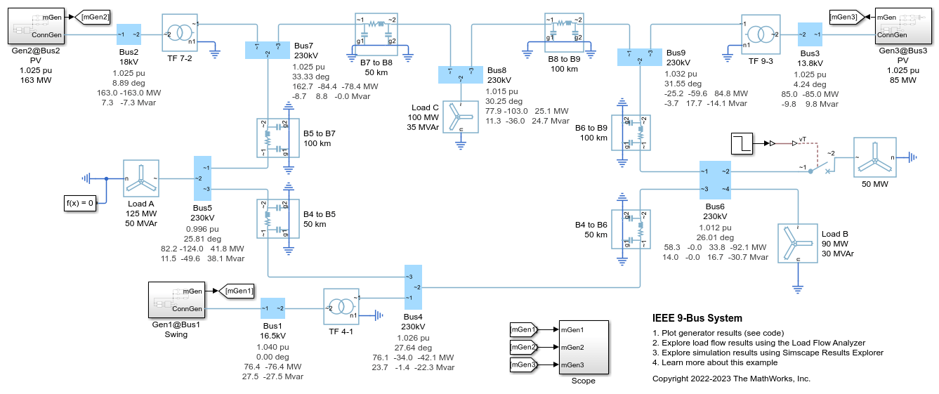
IEEE 9-Bus System
Model a 9-bus three-phase power system network. This example is based on the IEEE® benchmark test case. For more information, see "Power System Control and Stability" by P. M. Anderson and A. A. Fouad (IEEE Press, 2003).
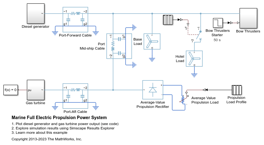
Marine Full Electric Propulsion Power System
A representative marine half-ship electrical power system with base load, hotel load, bow thrusters and electric propulsion.
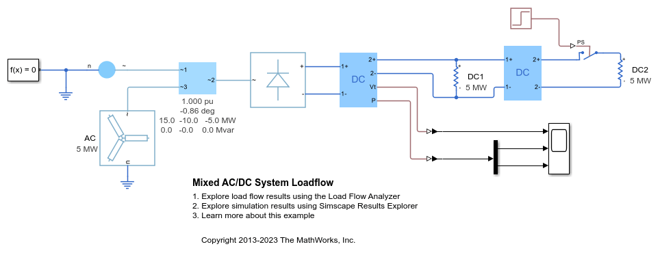
Mixed AC/DC System Loadflow
Use the Load Flow Analyzer to review the load flow results of a mixed AC/DC system. The model to which this analysis is applied includes an AC load flow source, a three-phase rectifier, and three loads. One of the loads is AC, one is permanently connected on the DC side, and one is switched on the DC side.