Earthing Effects with Unbalanced Load
This example shows the effects of three different types of earthing connections on network voltages and currents.
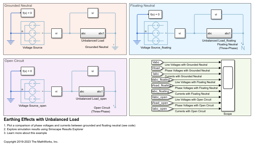
In each three-phase network, an AC voltage source drives a resistive load. A subsystem with two Variable Resistor blocks models the load.
This example models the earthing connection in each network by using a Grounded Neutral (Three-Phase), Floating Neutral (Three-Phase), or Open Circuit (Three-Phase) block.
Initially the load is balanced. At 0.05 s, the resistance on phase-a increases from 1 to 3 Ohms. At 0.07 s, the resistance on phase-c increases from 1 to 1.5 Ohms. The resistance on phase-b does not change during the simulation.
Model
Simulation Results from Simscape Logging
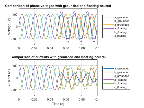
These plots show the phase voltages and phase currents in three-phase unbalanced loads under various grounding options.
Up to 0.05 seconds, there is no difference in phase voltages and phase currents between the conditions of the grounded neutral and floating neutral. At 0.05 seconds, the load becomes unbalanced, and the current flowing through the load changes for both conditions. However, the phase voltage in the case of neutral grounding remains constant throughout the simulation because the load is effectively grounded, unaffected by the unbalancing of the three-phase load.
Under the floating neutral condition, when the load becomes unbalanced, the phase voltages change significantly. In this case, if the system is monitoring only the line-to-line voltage, an undesirable overvoltage could occur in the unmeasured phase voltages. As a result, overheating, rapid deterioration of insulating materials, and other system issues might arise.
Results from Real-Time Simulation
This example has been tested on these platforms:
Speedgoat™ Performance real-time target machine with an Intel® 3.5 GHz i7 multi-core CPU and 4 GB RAM.
dSPACE® SCALEXIO LabBox with Intel® Core XEON E3-1275v3 at 3.5GHz and 4 GB RAM.
You can run this model in real time with a step size of 30 microseconds by using the Simscape local solver. For small sample rates, a task overrun might occur during the initial task execution due to a cold cache. To avoid this overrun, if the selected platform supports these options, relax the start-up behavior by specifying a limited number of task overruns or increasing the sample time of periodic tasks during the start-up phase of the real-time application.
See Also
Grounded Neutral (Three-Phase) | Floating Neutral (Three-Phase) | Open Circuit (Three-Phase) | Variable Resistor