Main Content

IEEE 9-Bus System

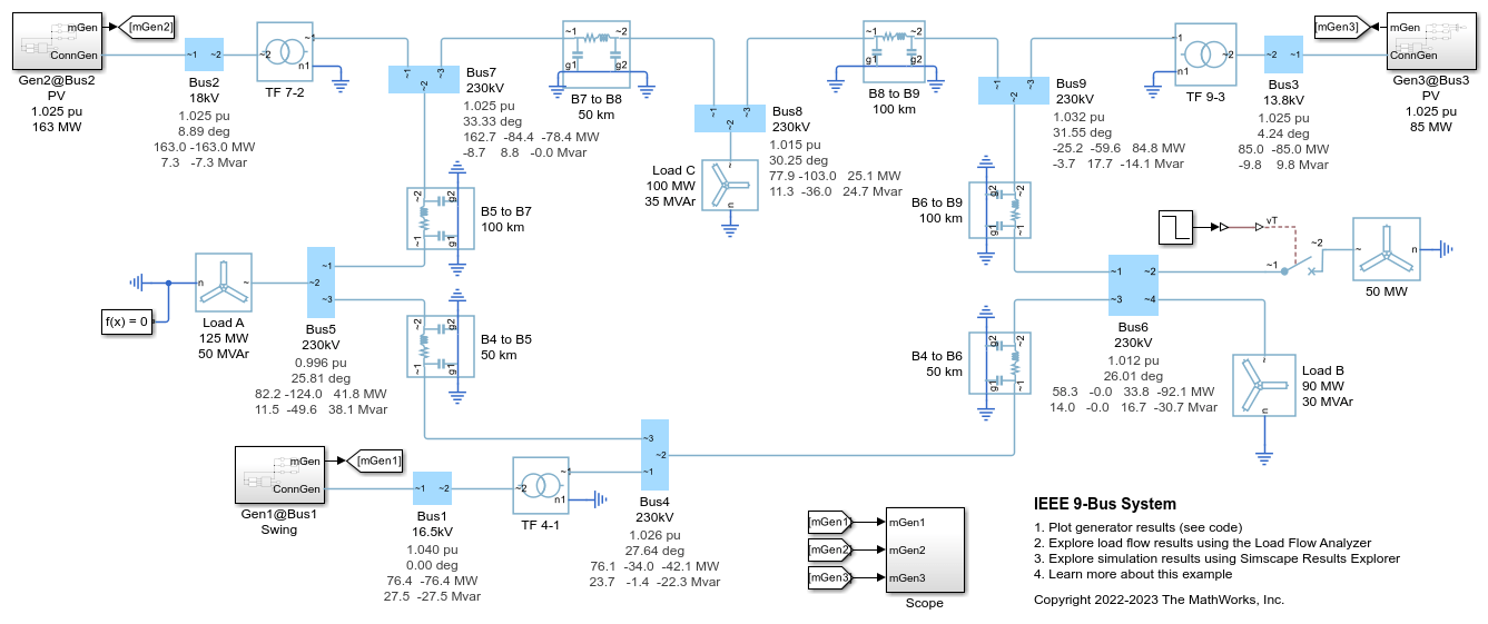
This example shows how to model a 9-bus three-phase power system network. This example is based on the IEEE® benchmark test case. For more information, see "Power System Control and Stability" by P. M. Anderson and A. A. Fouad (IEEE Press, 2003)

There are three generator subsystems in the model. Each of them comprises a synchronous machine and associated automatic voltage regulator (AVR), exciter, power system stabilizer (PSS), governor, and prime mover.

Simscape™ Electrical™ first performs a load-flow analysis for the model and determines the steady-state operating point for a given loading condition. For each generator subsystem, you can use the initial load flow solution to determine the initial field circuit voltage and current value for the AVR and the initial torque value for the governor. To determine these initial conditions, right-click a synchronous machine block and select Electrical->Display Associated Initial Conditions. This prints the initial field circuit voltage, the initial field circuit current, and the initial mechanical torque in MATLAB® Command Window.

The simulation then starts from this steady-state operating point. At time 10 s, an additional load is applied at Bus-6. After the simulation, the resulting load-flow solution is appended to each of the busbars.

Model Overview

Simulation Results from Simscape Logging

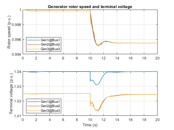
This plot shows the rotor speed and terminal voltage of Generator-1 at the swing bus, Bus-1, and the rotor speed and terminal voltage of Generator-2 and Generator-3 at the PV buses, Bus-2 and Bus-3.

References

[1] P. M. Anderson and A. A. Fouad, Power System Control and Stability, 2nd ed. Piscataway, NJ: IEEE Press; Wiley-Interscience, 2003.