反相拓扑降压-升压转换器控制
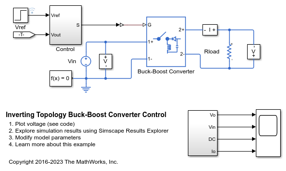
此示例展示了如何控制反相拓扑降压-升压转换器的输出电压。反相拓扑降压-升压转换器仅使用单个开关,输出电压的极性与输入相反。为了调整占空比,Control 子系统使用基于 PI 的控制算法。在整个仿真过程中,输入电压和系统负载被视为保持恒定。总仿真时间 (t) 为 0.25 秒。在 t = 0.15 秒时,参考电压发生变化,系统从降压模式切换为升压模式。
模型

来自 Simscape 记录的仿真结果
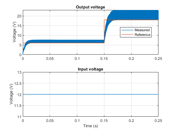
下图显示了测试中的请求电压和测得电压,以及电路中的输入电压。

此示例展示了如何控制反相拓扑降压-升压转换器的输出电压。反相拓扑降压-升压转换器仅使用单个开关,输出电压的极性与输入相反。为了调整占空比,Control 子系统使用基于 PI 的控制算法。在整个仿真过程中,输入电压和系统负载被视为保持恒定。总仿真时间 (t) 为 0.25 秒。在 t = 0.15 秒时,参考电压发生变化,系统从降压模式切换为升压模式。

下图显示了测试中的请求电压和测得电压,以及电路中的输入电压。
