LC Transmission Line and Test Bridge
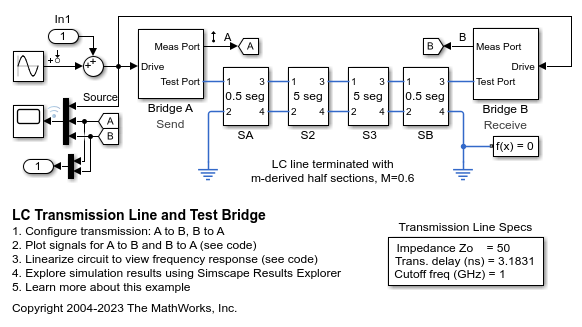
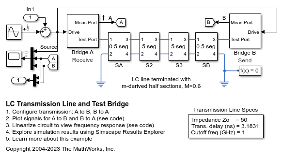
This model shows a transmission line model and bi-directional test bridge. Reflected and transmitted signals are slightly different if the test direction is changed. This is because the line model is not symmetric. This type of model can be used both to explore the impact of cable choice on transmission characteristics, and also to compare relative fidelity of different transmission line model structures and parameterizations.
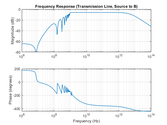
This model can be used to obtain the frequency response of the system. MATLAB® command linmod can be used to linearize the model. If you have Simulink® Control Design™, open the model LCLineTestBridge. To open the Model Linearizer, on the Apps tab, under Control Systems, click Model Linearizer.
Model

Bridge A Subsystem

5 Segments (S2 Subsystem)

Simulation Results from Simscape Logging
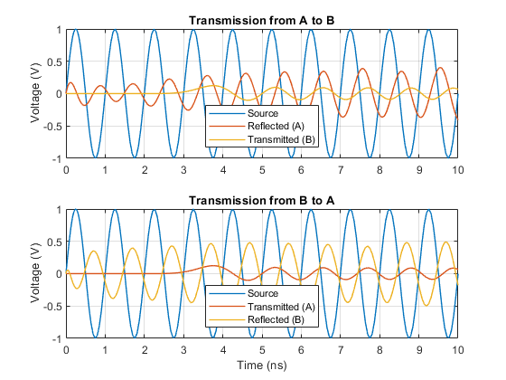
The plots below show the source, transmitted, and reflected signals for transmission tests from A to B and from B to A. Because the transmission line is asymmetric, differences can be seen in the reflected signals.

Frequency Response


