Marine Power System Deployment to HIL
This example shows a marine power system model suitable for multirate Hardware-In-the-Loop (HIL) deployment. The example uses the Simscape™ Network Couplers Library to split the model into separate Simulink® subsystems that you can deploy at different sample rates. This allows you to run parts of the system (here, for example, the turbines) with a slower sample time and reduce overall computational cost.
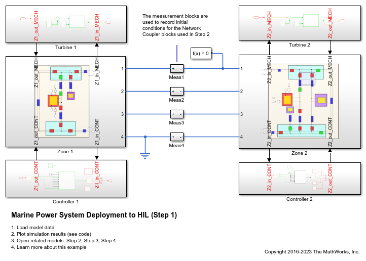
Step 1: Design Model
This figure shows the top-level design model. The power system comprises two separate electrical zones, each with its own steam generator, controllers, and local loads. The model already has different sample times for the electrical, mechanical, and controller parts. However, it is configured to run as a single simulation thread, either for desktop simulation, or for deployment on a real-time target.
Now run the simulation to generate some validation data using the unmodified model.
Simulating MarineHIL
Depending on real-time hardware capability, a large model like this might not run in the available frame time. In this case, you can separate the model into smaller parts and distribute them across multiple processors. Here the model is split into four separate tasks that you can run on different cores.
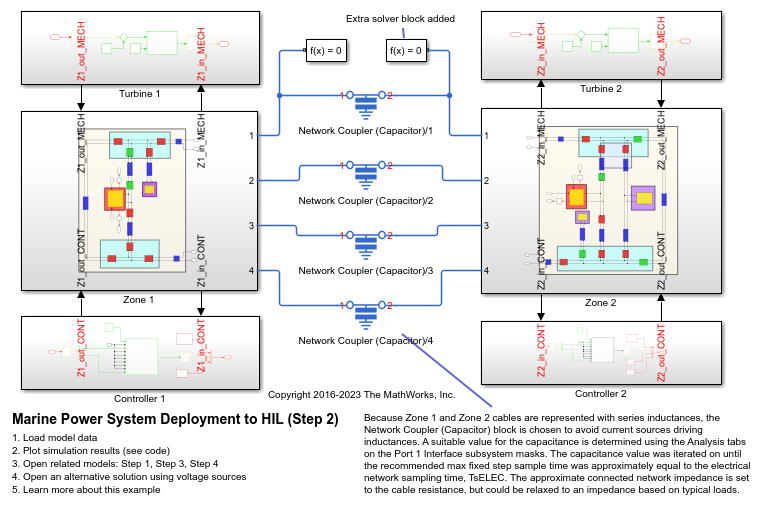
Step 2: Split the Electrical Network
This figure shows how the Network Coupler (Capacitor) block separates the two zones by using the capacitor integrator to separate an algebraic voltage constraint. An alternative solution for this model is to use the Network Coupler (Voltage-Voltage) block, which uses voltage measurements from the last sample time to keep the two networks synchronized. This maintains numerical stability through careful choice of an internal impedance for each voltage source.
You must carefully set the initial conditions for the coupler blocks when splitting a physical network. This is because the decoupled networks are initialized separately by Simscape. The initial voltages and currents from Step 1 are used to set initial conditions on each of the Network Coupler blocks.
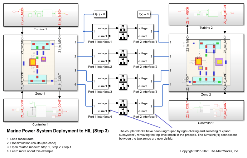
Step 3: Ungroup and Redraw
In this step all of the Simscape Network Coupler Library blocks are first unmasked and then their contents moved up a level using the Subsystem && Model Reference -> Expand Subsystem option from the right-click context menu. This makes the Simulink connections visible at the top level, along with the rate transition blocks. You can then group the blocks and subsystems together by sampling time.
Step 4: Deployment Model
In this final step the subsystems are converted to model reference blocks and six periodic tasks are defined. You can now simulate the model using multiple cores or by deploying to multiple microprocessors.
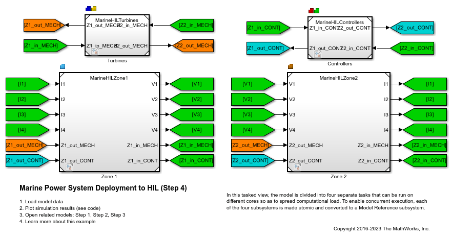
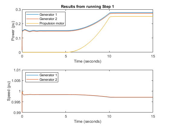
This figure shows the response of the two generators when the main propulsion system is started. You can compare the results against the same results generated in Step 1 and confirm that the deployment steps do not significantly change behavior.
Simulating MarineHILStep4
