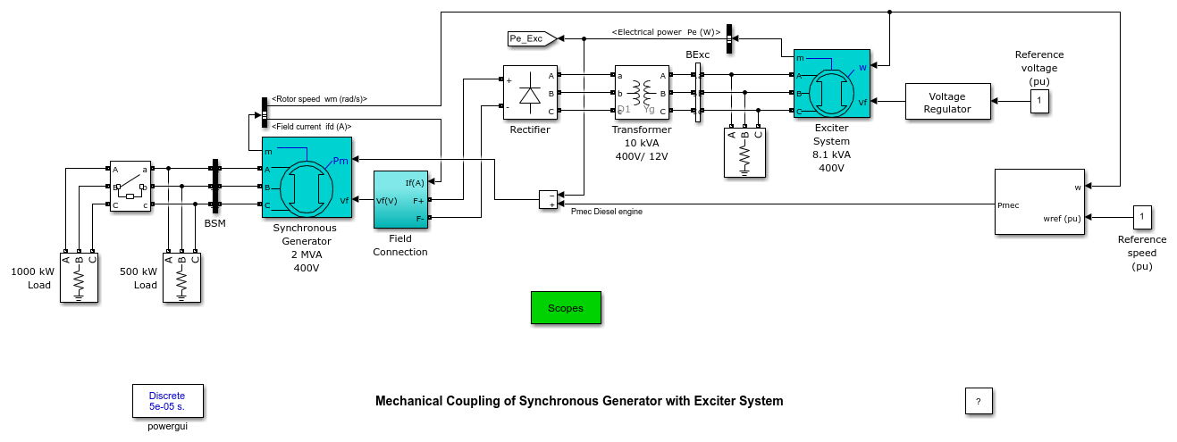
Mechanical Coupling of Synchronous Generator with Exciter System
This example shows a Machine mechanical coupling of an excitation system.
Gilbert Sybille, IREQ.

Description
In large alternators, the excitation system is provided by a small synchronous machine connected on the same shaft as the main synchronous generator. Current rectification is performed by a rotating diode bridge mounted on the synchronous machine shaft, thus avoiding slip rings for providing DC power to the synchronous generator field. Mechanical coupling of the Synchronous generator and the Exciter is done by using speed as mechanical input for the Exciter machine.
The Exciter is a small synchronous machine rated 8.1 kVA, 400 V, 50Hz, 1500 RPM. A 400V / 12 V transformer is used to adapt the 400 V output voltage of the exciter to the rectifier. In real life this transformer would not be used. Instead, the Exciter output voltage would rather be 12 V. The output of the rectifier bridge is connected directly to the synchronous generator field terminals. Filtering is not required because of the large field inductance.
The synchronous generator is a 2 MVA, 400V, 50 Hz, 1500 rpm machine driven by a diesel motor. A nominal field current (Ifn) of 100A specified in the mask parameters allows using the real voltage applied to the rotor (not the field voltage seen from stator). It results in a nominal field voltage of 9.2837 V. The field terminal voltage of the synchronous generator is measured inside the "Field Connections" subsystem. This subsystem is required to interface the input Vf of the synchronous machine and the real field terminals. It uses a current source driven by the DC current output of the bridge which also corresponds to the DC field current. The voltage appearing across this current source corresponds to the field voltage which must be applied to the Vf Synchronous Machine input.
Voltage regulation of the generator is performed by controlling the field voltage of the exciter. The Diesel engine provides the total mechanical power required by the main synchronous machine and the exciter.
Simulation
Run the model and observe signals on the Synchronous Generator Scope block. From 0 to 3 sec the synchronous machine delivers 500 kW (25 % of rating). At t=3 sec, an additional 1000 kW is switched on by closing the circuit breaker. In order to keep voltage at 1 pu, the excitation current increases from 112 A to 185 A (trace 1). The field voltage (trace 2) contains a 300 Hz ripple, but this ripple does not appear in the field current because of the large field inductance. Trace 3 shows that after load switching the synchronous machine terminal voltage resumes to its nominal value after a 3 second transient. Traces 4 and 5 show the mechanical output power of the diesel engine and the speed of the engine-generator set. Speed regulation maintains 1 pu speed and nominal frequency (50 Hz output voltage).