Microgrid with Electric Vehicles V2G (Vehicle-to-Grid) Support
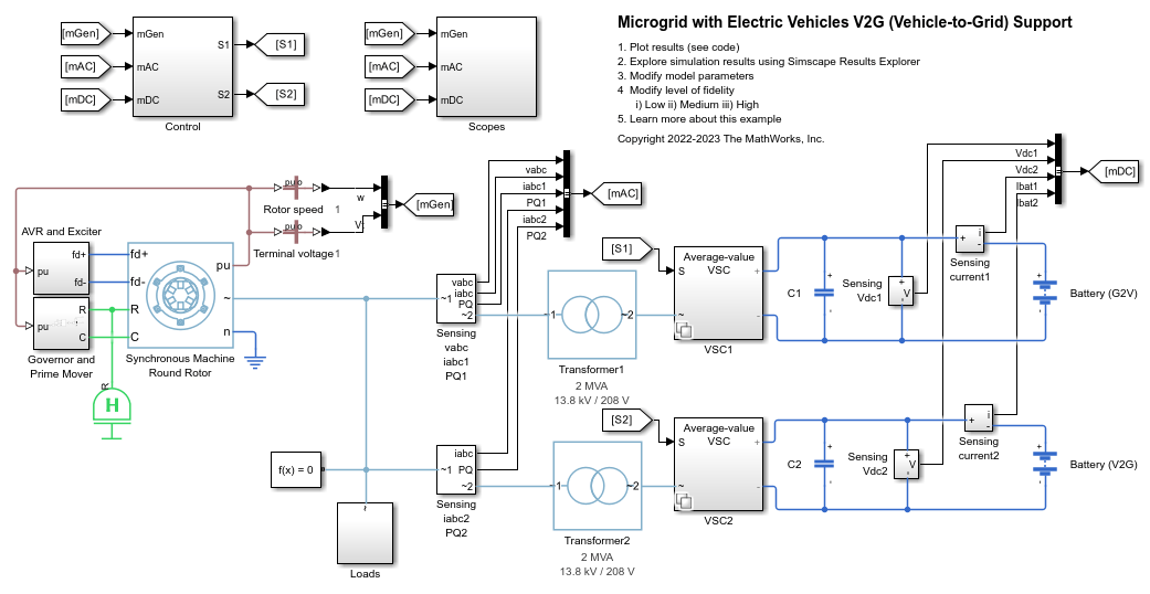
This example shows how to model a microgrid and how to regulate its frequency by using vehicle-to-grid (V2G) support from electric vehicles (EVs).
Open Model
The microgrid comprises one synchronous generator and two groups of electric vehicle batteries. Each battery block represents 20 EVs plugged into the grid. The range of grid frequency is set between 0.999 and 1.001 per unit. In this example, the Battery (G2V) block models EVs with a state-of-charge less than 80%. These EVs are always charged. The Battery (V2G) block models EVs with a SOC higher than 90% that provides V2G support during periods of peak demand in the grid.
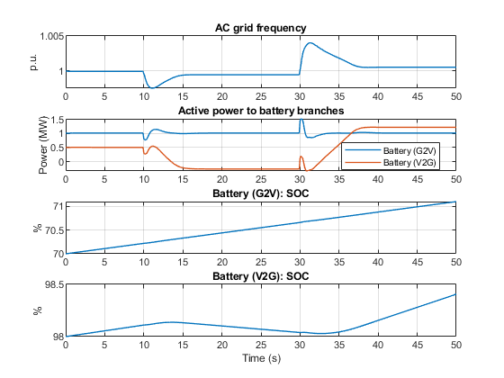
Initially, two batteries are charged and obtain power from the grid. Their SOCs increase from an initial value of 70% and 98%, respectively. At time 10 s, the connection to the grid of a 1 MW load causes the grid frequency to drop below 0.999 per unit. The Battery (V2G) block starts to discharge and supply power to the grid. As a result, the grid frequency increases to the pre-set range (0.999 ~ 1.001 per unit). At time 30 s, the disconnection from the grid of a 2 MW load causes the grid frequency to rise above 1.001 per unit. The Battery (V2G) block goes back to charge status and the grid frequency decreases to the pre-set range. The Battery (G2V) block is being charged during the simulation since its SOC is less than 80%.
Model Different Levels of Details Using Variant Controls
The MicrogridEVToGridData.m file creates variant controls for voltage source converter and converter controller. Specifically, the file defines these Simulink.Variant objects:
AverageValueVSCandSwitchingVSC, used with the average-value and switching voltage source converter.ControllerTimeModeandControllerFrequencyAndTimeMode, used with the time and frequency-and-time simulation mode.
The file also defines a fidelity variable that specifies the level of fidelity.
In this example, there are three different levels of fidelity:
Low - The example runs in frequency-and-time simulation mode. An average-value voltage source converter models the converter. The sample time is 0.1 s.
Medium - The example runs in time simulation mode. An average-value voltage source converter models the converter. The sample time is 200 us.
High - The example runs in time simulation mode. Ideal power electronic devices model the converter. The sample time is 2 us.
You can change the level of fidelity in the MicrogridEVToGridVariantControl.m file. The sample time and simulation mode are configured accordingly.
View Simulation Results from Simscape Logging
This plot shows the AC grid frequency, the active power that flows to two battery branches, and the state of charge of batteries in low level of fidelity.
Results from Real-Time Simulation
This example, with level of fidelity set to Low, has been tested on these platforms:
Speedgoat™ Performance real-time target machine with an Intel® 3.5 GHz i7 multi-core CPU and 4 GB RAM.
dSPACE® SCALEXIO LabBox with Intel® Core XEON E3-1275v3 at 3.5GHz and 4 GB RAM.
You can run this model in real time with a step size of 3 milliseconds by using the Simscape local solver. For small sample rates, a task overrun might occur during the initial task execution due to a cold cache. To avoid this overrun, if the selected platform supports these options, relax the start-up behavior by specifying a limited number of task overruns or increasing the sample time of periodic tasks during the start-up phase of the real-time application.
See Also
Synchronous Machine Round Rotor | Battery | Average-Value Voltage Source Converter (Three-Phase) | Converter (Three-Phase)