Kundur's Two-Area System with PMU
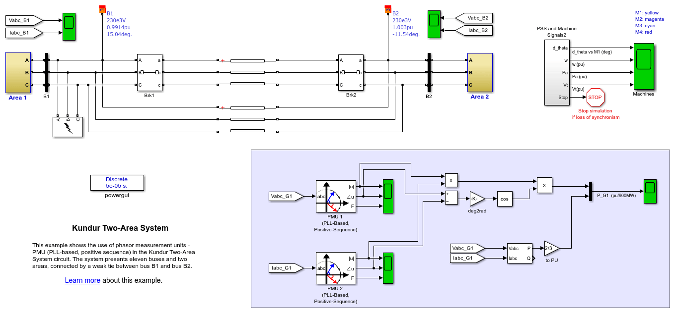
This example shows the use of the PMU (PLL-Based, Positive-Sequence) block within the Kundur's Two-Area System.
Description
The Kundur's Two-Area System used in this example can be found on page 813 in the textbook 'Power System Stability and Control', written by P. Kundur [1]. Figure below shows basic topology.
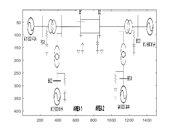
The system presents eleven buses and two areas, connected by a weak tie between bus B1 and bus B2.
Two loads are applied to the system at buses B1 and B2. In addition, two shunt capacitors are also connected to bus B1 and bus B2 as shown in the topology above.
Simulation
In Model Configuration Parameters, select 'Fixed-step' as simulation type and 'Discrete' as solver.
PMU sample time is Ts_PMU = 1/60/64 = 20.42 us. However, the network model sample time Ts = 50 us.
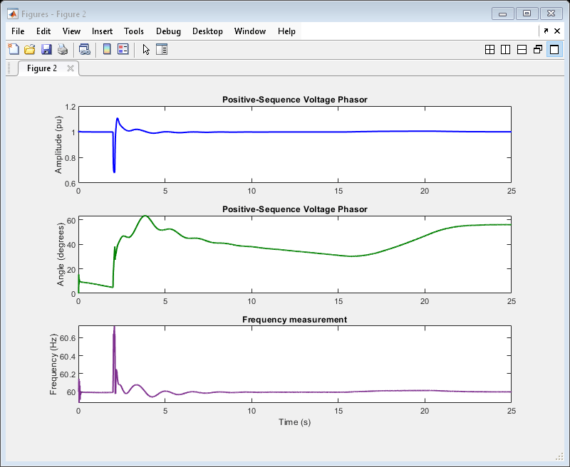
Open the scopes and start the simulation. Zoom on voltage and current phasors right after the fault occurs and notice the transient.
A three-phase fault occurs at 2 seconds of simulation. After 0.10 seconds, the three-phase fault is cleared and a new steady-state is presented until the end of the simulation at 25 seconds, as shown in the plot below.
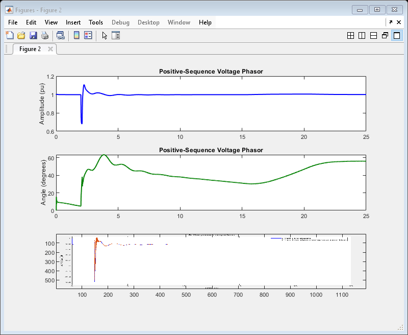
Change the reporting rate factor and the sampling rate. Compare the shape of the waveforms shown on the scope.
Finally, compare the active power computed from the PMU phasors with the three-phase instantaneous power block. The plot below shows how the waveforms match, particularly during fault condition.
References
[1] P. Kundur, N. J. Balu, and M. G. Lauby, Power system stability and control, vol. 7. McGraw-hill New York, 1994.
You can also select a web site from the following list
Americas
- América Latina (Español)
- Canada (English)
- United States (English)
Europe
- Belgium (English)
- Denmark (English)
- Deutschland (Deutsch)
- España (Español)
- Finland (English)
- France (Français)
- Ireland (English)
- Italia (Italiano)
- Luxembourg (English)
- Netherlands (English)
- Norway (English)
- Österreich (Deutsch)
- Portugal (English)
- Sweden (English)
- Switzerland
- United Kingdom (English)
Asia Pacific
- Australia (English)
- India (English)
- New Zealand (English)
- 中国
- 日本Japanese (日本語)
- 한국Korean (한국어)