Dual Active Bridge Converter DC/DC Converter
This example shows the operation of a single-phase Dual Active Bridge (DAB) DC/DC converter.

Description
The single-phase Dual Active Bridge (DAB) converter is a highly efficient isolated bidirectional DC-to-DC converter. Its key features are:
Isolated operation
Power density (high frequency operation reduces the size of the isolation transformer)
Bidirectional power flow
Efficiency (Zero Voltage Switching)
It is used in several applications such as in charging stations and electric vehicle traction. Vehicle-to-Grid (V2G) systems are also using this type of converters. The 10-kW DAB model consists of two MOSFET full-bridges linked by a coupling inductor and a high frequency transformer. The high voltage bridge is connected to an 800V DC source and the low voltage bridge is connected to a 450V DC source. Both bridges are controlled by a pulse generator and a current regulator.
DAB Operation
Power flow in the DAB is achieved by phase-shifting the pulses of one bridge with respect to the other, while keeping the duty cycle of both bridges at 50%. Note that identical pulses are sent to the diagonal switches. In our example, the switching frequency is set to 100 kHz and the dead time to 150 ns. The theoretical output power transfer between the two bridges is given by:

where:
 is the DC link voltage of the high voltage bridge, in Volts
 is the primary to secondary transformer voltage ratio
 is the DC link voltage of the low voltage bridge, in Volts
 is the phase shift between the two square waves of the bridges, in Radians
 is the PWM switching frequency, in Hertz
 is the total inductance (coupling inductor + total transformer leakage reactance seen from the primary) between the two bridges, in Henry.
We can see that the power transfer between the two bridges can be controlled by changing the angle of the two square waves of the bridges. For a positive angle  , power will be transferred from the high-voltage bridge to the low-voltage bridge. Power flow will be reversed for a negative angle
  . The figure below shows the bridges voltages and the resulting coupling inductor current during the four switching states while angle
  is set to +22 degrees.

Simulation
The model allows running two simulation:
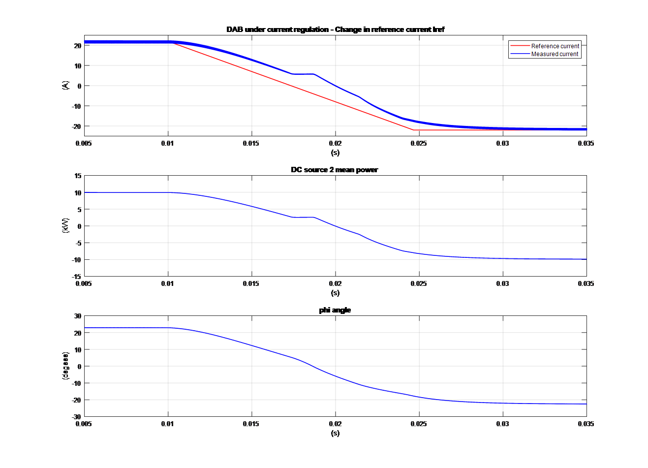
First, activate the current regulation mode by setting the value of the Control Mode block to zero. Run the simulation and observe the DAB current regulator dynamics on Scope phi_P2_kW. The reference current is changed from 22 A to -22 A at 0.01s (at a slew rate of 3000 A/s). In order to follow the new reference, the regulator output will vary from 22.9 degrees to -22.5 degrees.
Now set the value of the Control Mode block to 1 to allow direct control of the pulse generator input (phi_deg) to ramp the angle
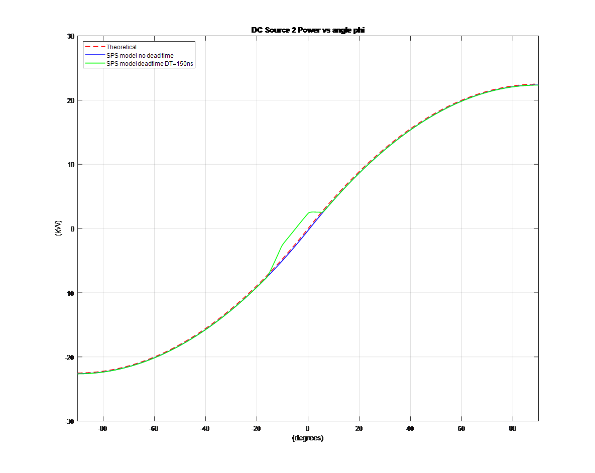
 from -100 to 100 degrees. In the Additional Scopes subsystem, open the Scope_P2_Ptheo_kW and run the simulation. You will see the actual power delivered to DC Source 2 compared to the calculated theoretical value while the angle
  is ramped from -100 to 100 degrees. For an angle
  ranging from -15 to +5 degrees, the actual power transfer does not match the theoretical value. This is mainly due to the 150 ns dead time. Figure below shows the simulation results as well as a third curve (blue curve) showing the power transfer resulting from another simulation performed without dead time. This blue curve and the theoretical value curve are almost identical.

References
Texas Instruments TIDA-010054 Bi-directional, Dual Active Bridge Reference Design for Level 3 Electric Vehicle Charging Stations. June 2019. https://www.ti.com/tool/TIDA-010054
Rawad Zgheib, Innocent Kamwa, Kamal Al-Haddad, "Comparison between Isolated and Non-Isolated DC/DC Converters for Bidirectional EV Chargers ", IEEE 2017. https://ieeexplore.ieee.org/document/7913285
