Overcurrent Relay Protection in AC Microgrid
This example shows how to model an overcurrent relay in an AC microgrid. You can use this example to study overcurrent relay coordination in a microgrid. The Relay block comprises two protection units, phase protection and earth protection. The phase protection unit protects the microgrid from high phase currents. The earth protection unit protects the microgrid from high earth currents. In this example the relay2 block protects the distribution_line2 block. The relay1 block protects the distribution_line1 block and also acts a back-up for the relay2 block. If a fault occurs on the distribution_line2 block and the relay2 block doesn't operate, the relay1 block operates after a specified time and isolates the system. To avoid tripping of the system, the relay1 and relay2 blocks operate such that only one relay operates at any given time. You can specify either time multiplier setting or the desired operating time of relay2 block.
Microgrid Overview
The figure below shows an AC microgrid with a source, transformer, distribution lines, current transformers, circuit breakers, overcurrent relays, and loads.
The microgrid is connected to the grid at 132 kV. A three-phase transformer steps down the source voltage from 132 kV to 33 kV.
The current transformer blocks step down the current within the operating range of the overcurrent relays. The relay1 and relay2 blocks send trip signals to the circuitBreaker1 and circuitBreaker2 blocks, respectively.

Current Transformer Overview
In this example, the current transformer comprises three single-phase transformer blocks. A 1 ohm resistor is placed in series with the current transformer secondary winding and a voltage sensor measures the voltage across the resistor. This voltage is equal to the current flowing through the resistor. This example determines the turns ratio of the current transformers based on the load currents flowing through them and the safety factor. If a load current of 60A flows through the current transformer primary winding and the safety factor is equal to 0.25, the current transformer block ratio is equal to 100/1. You can specify the safety factor as an input. The secondary currents of the current transformer are inputs to the relay1 and relay2 blocks, respectively.
Overcurrent Relay Block Overview
The relay block comprises the two protection units, phase protection unit and earth protection unit. When the value of the current in any of the phases is greater than the pick up value, the phase protection unit triggers the trip signal. When the value of the zero sequence current is greater than the pick up value, the earth protection unit triggers the trip signal. When one of the units triggers the trip signal, the relay sends the trip signal to the circuit breaker with a time delay, called relay operating time. The relay operating time depends on the pick up value and the time multiplier setting of the relay. The Relay block has a total of 8 operating characteristics including standard IEC and IEEE characteristics, Definite time, and IvsT. You can calculate the relay operating time for standard IEC and IEEE characteristics by using this equation:
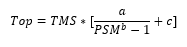
where TMS is the time multiplier setting, PSM is the plug setting multiplier, and a, b, and c are constants. If you select Definite time, directly specify the relay operating time. If you select IvsT characteristic, specify the operating time of the relay as a two dimensional matrix for different current values and time multiplier settings. The relay algorithm calculates the operating time for the specified time multiplier setting and pick up value.
Overcurrent Relay Settings
There is always a time delay between the operating time of the relay1 and relay2 blocks. Set the time delay by specifying the protection.tFactor in the OvercurrentProtectionInput MLX file. For example, if a fault occurs in the distributionLine2 block and the relay2 block fails to isolate it, the relay1 block sends the trip signal to the circuitBreaker1 block after a minimum time delay equal to the value you specified in the protection.tFactor parameter. If you select standard IEC or IEEE characteristics, the system estimates the relay1 time settings based on the time settings of the relay2 block. If you specify the time multiplier setting of the relay2 block, the system estimates the time multiplier setting of the relay1 block. If you specify the operating time of the relay2 block, the system estimates both the time multiplier setting of the relay2 and relay1 blocks. A maximum short circuit current in the distributionLine2 block happens when a fault occurs at the start of the distribution line.
In this example, the phase current value is maximum during phase-to-ground (L-G) fault and the earth current is maximum during two-phase-to-ground(L-L-G) fault. To estimate the relay time settings, L-G fault is considered for phase protection and L-L-G fault is considered for earth protection. This equation calculates the fault current in per-unit during the L-G fault:
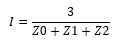
where Z0, Z1, and Z2 are the zero sequence, positive sequence, and negative sequence impedances. This equation calculates the zero sequence current during the L-L-G fault:
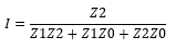
where Z0, Z1, and Z2 are the zero sequence, positive sequence, and negative sequence impedances.
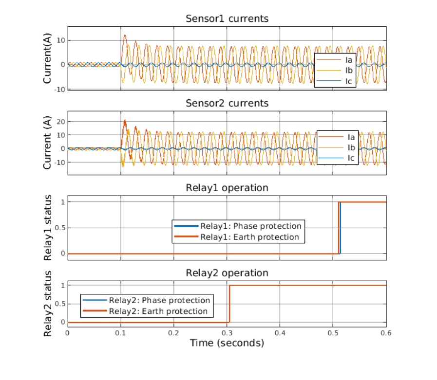
Relay Operating Time for a Phase to Ground(L-G) Fault
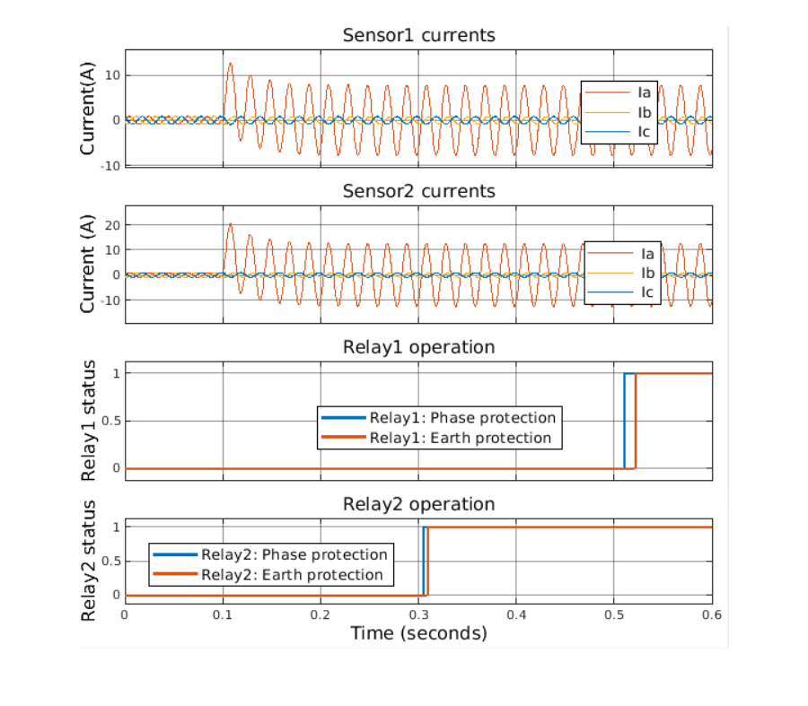
The figure below shows the current transformer secondary currents and the operating time of the relay1 and relay2 blocks for an L-G fault at 0.1 km on the distributionline2 block. The fault occurs at 0.1 s. IEEE moderately inverse characteristics are selected for the phase protection and earth protection units for the relay1 and relay2 blocks. The operating time of the relay2 block is equal to 0.2 s. The time grading factor between the relay1 and relay2 blocks is equal to 0.2 s. The pick up values for phase protection of the relays are equal to 1 A. The pick up values for earth protection of the relays are equal to 0.05 A. To observe the operating time of the relay1 block, the circuit breaker protection is disabled.
Relay Operating Time for a Two-Phase to Ground(L-L-G) Fault
The figure below shows the current transformer secondary currents and the operating time of the relay1 and relay2 blocks for an L-L-G fault at 0.1 km on the distributionline2 block. The fault occurs at 0.1 s. IEEE moderately inverse characteristics are selected for the phase protection and earth protection units for the relay1 and relay2 blocks. The operating time of the relay2 block is equal to 0.2 s. The time grading factor between the relay1 and relay2 blocks is equal to 0.2 s. The pick up values for phase protection of the relays are equal to 1 A. The pick up values for earth protection of the relays are equal to 0.05 A. To observe the operating time of the relay1 block, the circuit breaker protection is disabled.
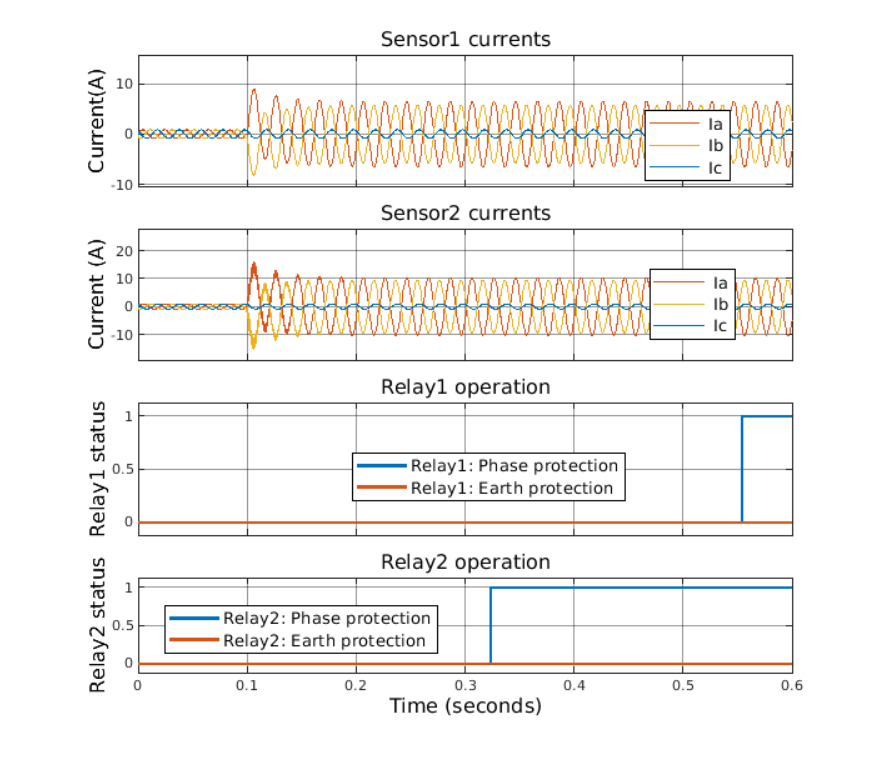
Relay Operating Time for a Two-Phase(L-L) Fault
The figure below shows the current transformer secondary currents and the operating time of the relay1 and relay2 blocks for an L-L fault at 0.1 km on the distributionline2 block. The fault occurs at 0.1 s. IEEE moderately inverse characteristics are selected for the phase protection and earth protection units for the relay1 and relay2 blocks. The operating time of the relay2 block is equal to 0.2 s. The time grading factor between the relay1 and relay2 blocks is equal to 0.2 s. The pick up values for phase protection of the relays are equal to 1 A. The pick up values for earth protection of the relays are equal to 0.05 A. To observe the operating time of the relay1 block, the circuit breaker protection is disabled.
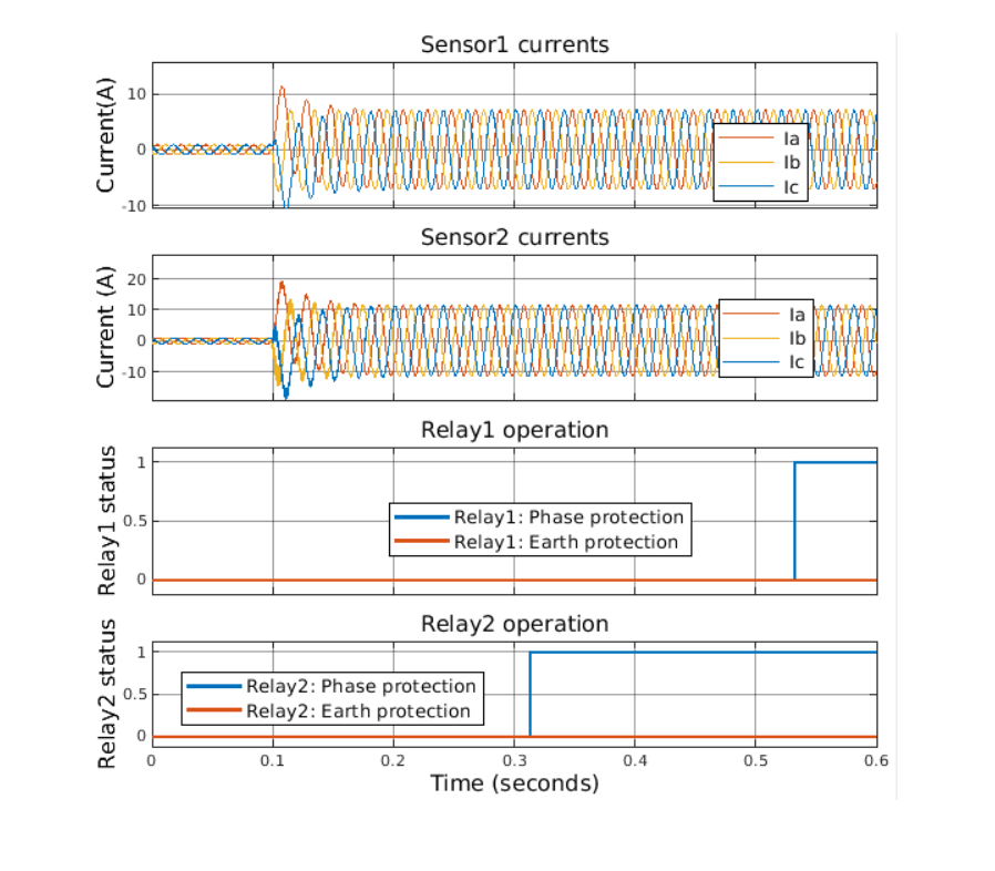
Relay Operating Time for Three-Phase(L-L-L) Fault
The figure below shows the current transformer secondary currents and the operating time of the relay1 and relay2 blocks for an L-L-L fault at 0.1 km on the distributionline2 block. The fault occurs at 0.1 s. IEEE moderately inverse characteristics are selected for the phase protection and earth protection units for the relay1 and relay2 blocks. The operating time of the relay2 block is equal to 0.2 s. The time grading factor between the relay1 and relay2 blocks is equal to 0.2 s. The pick up values for phase protection of the relays are equal to 1 A. The pick up values for earth protection of the relays are equal to 0.05 A. To observe the operating time of the relay1 block, the circuit breaker protection is disabled.
Relay Parameters Configuration
Relay characteristic for phase protection - Standard IEC and IEEE operating characteristics are included in the relay block. Choose between IEC normal inverse, IEC extremely inverse, IEC very inverse, IEEE moderately inverse, IEEE extremely inverse, IEEE very inverse, Definite time, or IvsT.
Relay characteristic for earth protection - Standard IEC and IEEE operating characteristics are included in the relay block. Choose between IEC normal inverse, IEC extremely inverse, IEC very inverse, IEEE moderately inverse, IEEE extremely inverse, IEEE very inverse, Definite time, or IvsT.
Fundamental frequency (Hz) - Rated frequency, in Hz. This value must be greater than zero.
Relay sample time (s) - Relay sampling time, in seconds.
*Relay operation enable - Whether to enable or disable the circuit breaker operation. Set this value to 1 to enable relay operation or 0 to disable relay operation.
Pick up value for phase protection (A) - Minimum current to trigger phase protection unit, in Ampere.
Pick up value for earth protection (A) - Minimum current to trigger earth protection unit, in Ampere.
Time multiplier setting for phase protection (s) - Time delay setting for phase protection unit, in seconds.
Time multiplier setting for earth protection (s) - Time delay setting for earth protection unit, in seconds.
Relay operating time for phase protection (s) - Time after which relay sends trip signal to circuit breaker, in seconds (To enable this parameter, set Relay characteristic for phase protection to Definite time).
Relay operating time for earth protection (s) - Time after which relay sends trip signal to circuit breaker, in seconds (To enable this parameter, set Relay characteristic for earth protection to Definite time).
Current setting for phase protection (A) - Current values for the lookup table, in Ampere (To enable these parameters, set Relay characteristic for phase protection to IvsT Characteristics).
Time multiplier setting for phase protection (s) - Time settings for the lookup table, in seconds.
Operating time for phase protection (s) - Relay operating time for phase protection, in seconds.
Current setting for earth protection (A) - Current values for the lookup table, in Ampere (To enable these parameters, set Relay characteristic for earth protection to IvsT Characteristics).
Time multiplier setting for earth protection (s) - Time settings for the lookup table, in seconds.
Operating time for earth protection (s) - Relay operating time for earth protection, in seconds.